The dashboard clock on my 2007 Toyota Yaris turned off after a few days of steadily losing brightness. This seems to be a common problem. A few people discussed it on the YarisWorld forums. After a lot of work I found the root cause and fixed the problem. My investigation and findings are described on the forum, but hopefully are more readable on this page.
Root cause
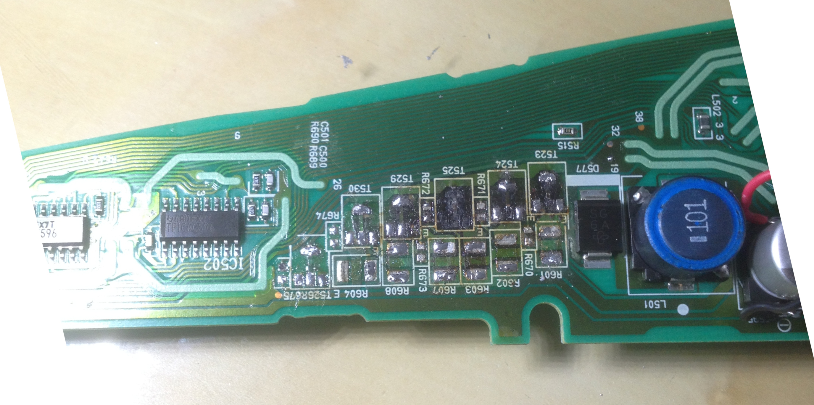
The vacuum fluorescent display (VFD) drive circuit uses an inefficient linear regulator design to provide energy to the filaments. The transistors produce a lot of heat and die after several years.
A VFD is a fairly complex system that I didn’t know about before investigating the problem, and my early attempts were to repair the existing power supply design. It turned out to be more reliable to replace it with a switched-mode power supply (a buck module).
How to disassemble the device to access the board that needs repairs
- take out the two side plastic parts (passenger airbag and warning button), these are just plastic clips so pull towards you starting from the bottom
- remove the cover of the speedometer by pulling towards you (takes some force)
- remove two screws holding the meter in place
- pull the meter out, you need to rotate/warp the plastic a little
- go back to your desk and remove 2 screws at the back of the unit + the clips
- pull the back of the unit, be careful there is a mirror inside that is going to fall off
- disconnect the “mainboard” (10x10cm board, just pull it out it will disconnect)
- remove 1 screw on the front cover, then remove the front cover (many clips)
- remove the plastic cover of the main display (4 screws + 1 clip + rotate it)
- disconnect the ribbon cable of the main display and note what path it takes
- you can now pull out the power board by removing the two clips and pulling towards you, which will disconnect the clock VFD
- the power board is the one that you need to fix
First attempt that didn’t work
Skip this if you’re only looking for how to solve it.
My first attempt worked, but didn’t last. I set out to replace the broken transistors.
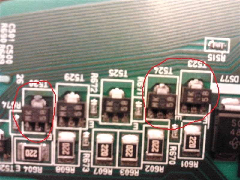
The MK markings seemed to be 2SB799 PNP transistors. I couldn’t source them so I bought an equivalent BCX53 reference. I replaced the 6 transistors, and the clock worked again. Total time for the fix was about 2 hours.
Sadly, after a few weeks, the clock died again, and the transistors appeared to have heated up even more than before. The board was more seriously burned than before, traces were torn, and so on. It was time for a more serious investigation.
My theory for why the repair wasn’t working is that this design relies on the board helping to dissipate some heat, and when it’s as badly burnt as mine it doesn’t dissipate as well. Of course as soon as 1 transistor dies the rest will follow due to the parallel design. Crappy power supply design that saved maybe 2 bucks.
So, instead of trying to fix this broken cheap power supply with such a terrible efficiency that the transistors dissipate multiple watts (about 500mW each, which is not nothing for SOT-89), let’s just replace it with something that works better.
The good fix
Just replacing the transistors doesn’t seem to work (because they’ll die again soon), so let’s figure out what they’re for exactly and take a higher level look: what is being implemented here?
The way they’re connected, the six transistors are basically in parallel and drive the cathode (the horizontal filaments) of the VFD. Their job seems to be to get a steady 300mA through these filaments (full brightness, figure empirically found with a bench power supply).
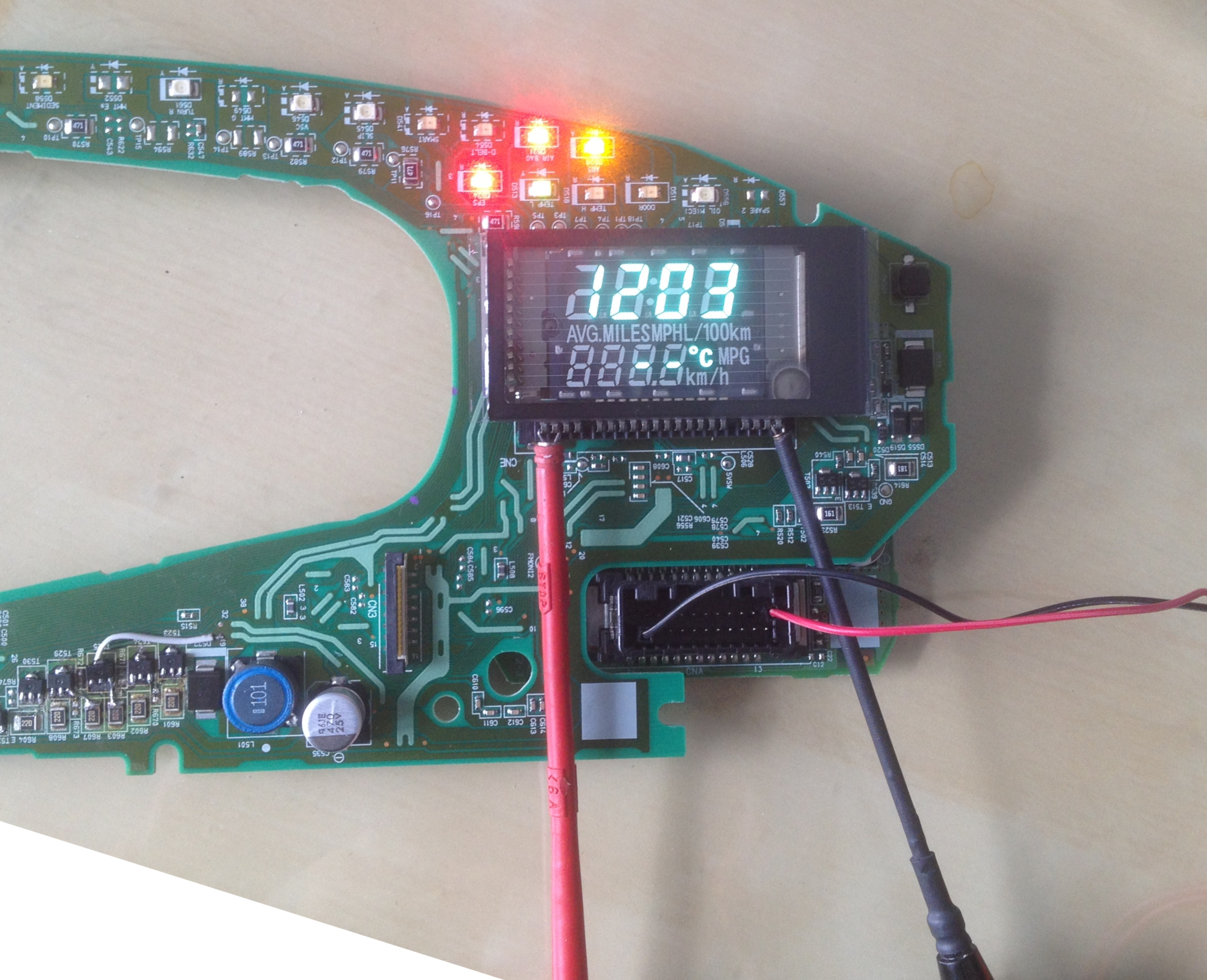
In fact, you can remove the 6 transistors, and connect a constant-current power supply set to 300mA between the + and - (leftmost and rightmost) pins of the VFD, while it’s plugged into the board - it will work normally.
I couldn’t fully work out how the transistors were driven (= what their base is connected to), but it all goes back to the mainboard and, on the power board, a pin that seems to be used to dim the VFD. I don’t remember it dimming when turning on the headlamps but maybe that’s actually what happens. My fix loses that feature, if it exists at all. No big deal.
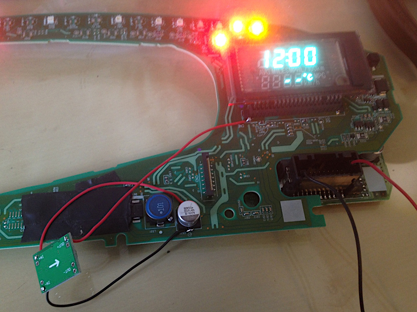
So if all we have to do is feed about 300mA to the filaments, we can remove all these transistors and plug in a cheap buck module instead set at the right voltage. I had an adjustable MP1584EN-based buck module (“D-Sun” chinese brand) lying around. These super common modules you can find for a few dollars. For example this one
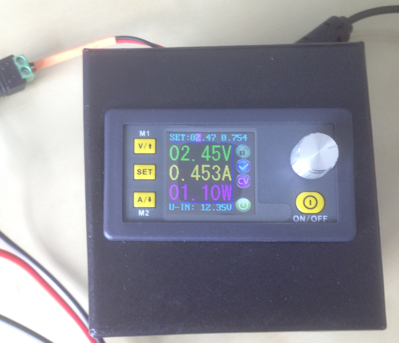
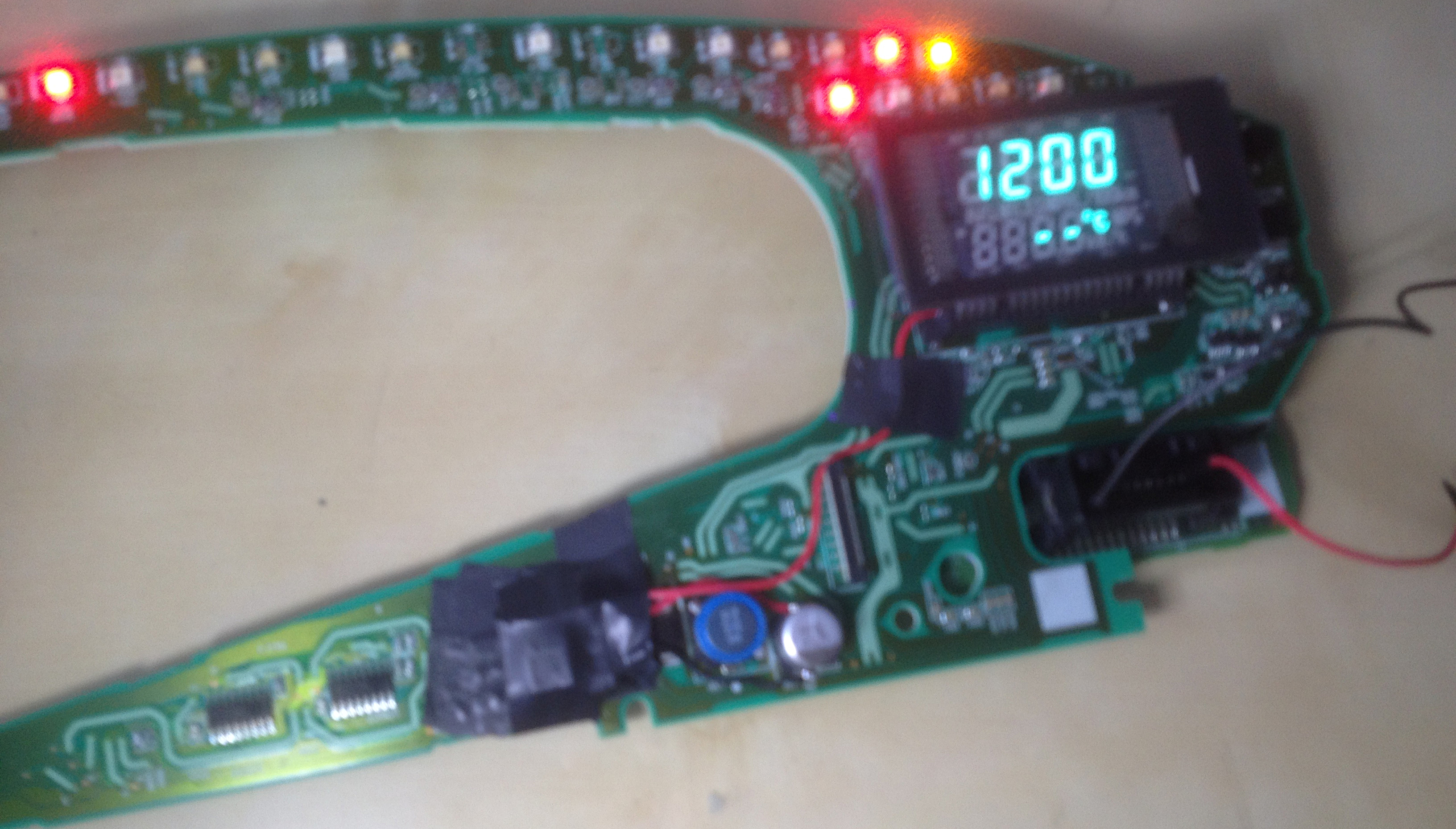
I used my poor man’s lab power supply to test what were the minimal voltage and currents needed to obtain full brightness, and I found out that a constant voltage 1.5V supply would yield a steady 300mA current that would correspond to full brightness. Going to 2.5V would increase current to 450mA without any visible change in brightness, and starting at 4V the filaments would glow red. (Sorry about the quality of my pictures, I was focused on solving the problem and only took the pics as an afterthought).

Once this was proven working, I cleared some space on the board by removing the transistors and their base and emitter resistors.
I laid out a layer of tape to insulate, soldered the module and taped it in place. This fits with room to spare when reassembling everything.
Sorry that the final picture is hard to read… The fix has now been working for a few weeks and I have little reason to doubt it will keep working.