Table of contents
- Monitoring gas consumption
- Constraints
- Architecture and hardware
- Hardware implementation and BOM
- Software
- Feedback and lessons learned
Monitoring gas consumption
I monitor my consumption of gas and electricity. I’ve covered electricity in a previous article (in French, because it only applies to meters from our national power company). The setup uses a Raspberry Pi and a custom electronics board to interface the meter to the Raspberry Pi. Here, we will use use the same Raspberry Pi for gas monitoring, associated to other elements.
Constraints
I have a Actaris G4 gas meter, located in the hallway outside of my apartment. For technical reasons, an electricity meter will always be located near a source of electricity and a place where networking cables can be installed - this is not the case for gas and water meters, which are usually located where no electricity is available, and no Ethernet cable is present. This implies that the system must be battery-powered and must use wireless transmission. Low power consumption will be a major objective, as I don’t intend to change batteries more than once a year. Another objective is for the system to be low cost. My budget is a total of about 35EUR.
Architecture and hardware
I may write a bit about it in the future, but I believe in a bottom-up approach. You look at what you have, what you can have, and from that you assess what you can build, amend/update the project goals and details in function of that, and then build your project. So I’ll always start from the low level because I believe this is the only way of actually finishing a project (= delivering something).
1-Getting data from the meter
How does the meter report data to us, anyway?
This model of gas meter (and apparently most models) has a small magnet mounted on one of the digits of the liter wheel. The magnetic field can be picked up by a sensor, in the very same way that bike speedometers work (magnet mounted on the wheel and detector on the fork). Additionally, the digit 6 is designed to reflect light very well. This can be picked up by another kind of sensor. Finally, we could try to use OCR. I’m sure some crazy (and incompetent) people have thought about it. I won’t elaborate as to why this is the worst idea.
Light
What sounds the easiest is to pick up the light reflected from digit 6. You need a LED, a photodiode, direct them both towards the front of the meter and you’re in business… but this is not a good idea for the following reasons:
- you are legally required not to hinder meter reading. The meter is the property of the gas company (in France, at least). If you put something in front of it, you’re bound to getting it ripped off, broken, stolen, or a combination of those.
- to detect a change in light reflection, you need to constantly emit light. The well-known CNY70 reflective sensor is built just for that. It costs several dollars apiece, is fairly bulky, and draws at least 1mA all the time (you have to keep the LED on). On a typical 2000mAH NiMH AA battery (I’ll write a separate article about why I’m sticking to this technology), that’s less than three months of autonomy, not accounting for the electronics.
- it requires placing the sensor at a very specific position and not ever opening the door again (for fear you’ll add some light into the sensor and make it no longer detect pulses). This is likely to be unreliable in the long run.
Magnetic
Going magnetic is a better solution. The Actaris G4 has a small depression intended for magnetic sensors. There are commercial ones, and homemade ones such as the one described there: https://www.flukso.net/content/actaris-g4-pulse. I built my own, naturally.
There are two technologies to detect a magnet passing in front of you. One of them is purely mechanical, the other is electrical.
Hall-effect sensor
Magnetic fields generate currents into conductors, and currents generate magnetic fields. One can use a Hall-effect sensor to generate an electrical signal when the magnet passes in front of the sensor. Unfortunately, those sensors are expensive, and are active: they constantly draw current (see the paragraph about reflective sensors). The datasheets are alsa a little much for my taste - there appears to be many different models of Hall-effect sensors, all of which with slightly different characteristics, and I just want this to work, not to receive a PhD in Hall effect.
Reed
A reed switch is made of two metal reeds inside a tiny glass bulb. The contacts will touch when a magnet is near them, making them electrically connect. This is completely passive: they draw no current, they cost next to nothing (fortunately so, because you will break many of them, so buy ten at once), and they provide a pretty clear numerical output instead of the questionable, comparator-requiring outputs of the other methods. So naturally, I went for reed switches. (Some people complain about debouncing, that is supposedly difficult to do correctly with a reed switch. It’s the easiest thing on the planet at least on this project. Read on.)
2-Transmitting data to a server = Raspberry Pi
Wireless data link
Wired transmission is out of the question. I had two solutions: storage onto a SD card that I would manually plug into the server every few months, or wireless transmission. That’s really only one solution :) Wireless transmission can be done in many different ways. There apparently are WiFi interfaces for Arduino! I shudder to think about the battery autonomy. Probably a few seconds. Then there are some more manageable protocols such as ZigBee, a bunch of proprietary protocols over the unlicensed 433MHz FM band (in Europe at least), and some others over the 2.4GHz band. The choice boils down to:
- will it
blendgo through two 60cm stone walls and 15 meters of hallways? - will it cost a lot?
- will it consume a lot of power?
I chose the nRF24L01+ transmitter, which is very inexpensive and - I found out after buying - goes across my walls without a problem. Mine come from there: http://yourduino.com/sunshop2/index.php?l=product_detail&p=188. You can’t possibly beat that price - competing solutions are easily 10 times more expensive. If you’re uncomfortable about buying from China, comfort yourself: everything is made there anyway. Might as well give money to the guys who make it rather than to the guys who import it. The nRF24L01+ (say it a few times, you’ll remember it) has a low power mode at about 1 micro-ampere, while the transmit (TX) mode is rated at 12mA (and receive mode - RX - at 14mA, this is counter intuitive but in radio, receiving costs more than emitting). We will not transmit all the time, we will actually transmit very little: once every pulse at most (and possibly a heartbeat packet so the server doesn’t think we’re dead), then immediately go back to sleep.
The bad news is that this chip talks over the SPI bus, which requires complex electronics to drive. We’ll need a microcontroller, a simple circuit will never be enough.
Microcontroller
We need a microcontroller. The wishlist is:
- cheap
- low power
- commercial boards available for the controller/clock/IO ports (I don’t design PCBs, I don’t want to learn)
- can be programmed with as little hardware as possible (USB->TTL serial adapter OK, standalone expensive programmer NOK)
- programmable in C (I know and like x86 assembly, I’m not immensely interested in learning others)
The first idea that comes to mind is naturally the Arduino platform. Commercial boards are definitely available. Cheap is debatable - the official boards are expensive, the cheap clones are OK. In terms of ease of programming Arduino is a world record (that’s why it succeeds). The real problem is the “low power” aspect. Most Arduino boards run over +5V and draw a lot of power. They’re also physically big and that is a problem for cases.
Then, you have the PIC family. I didn’t give it much thought - most people seem to design their own boards to use PICs with, and that’s not something I’m interested in. DIY is good, but one chooses what they want to do themselves.
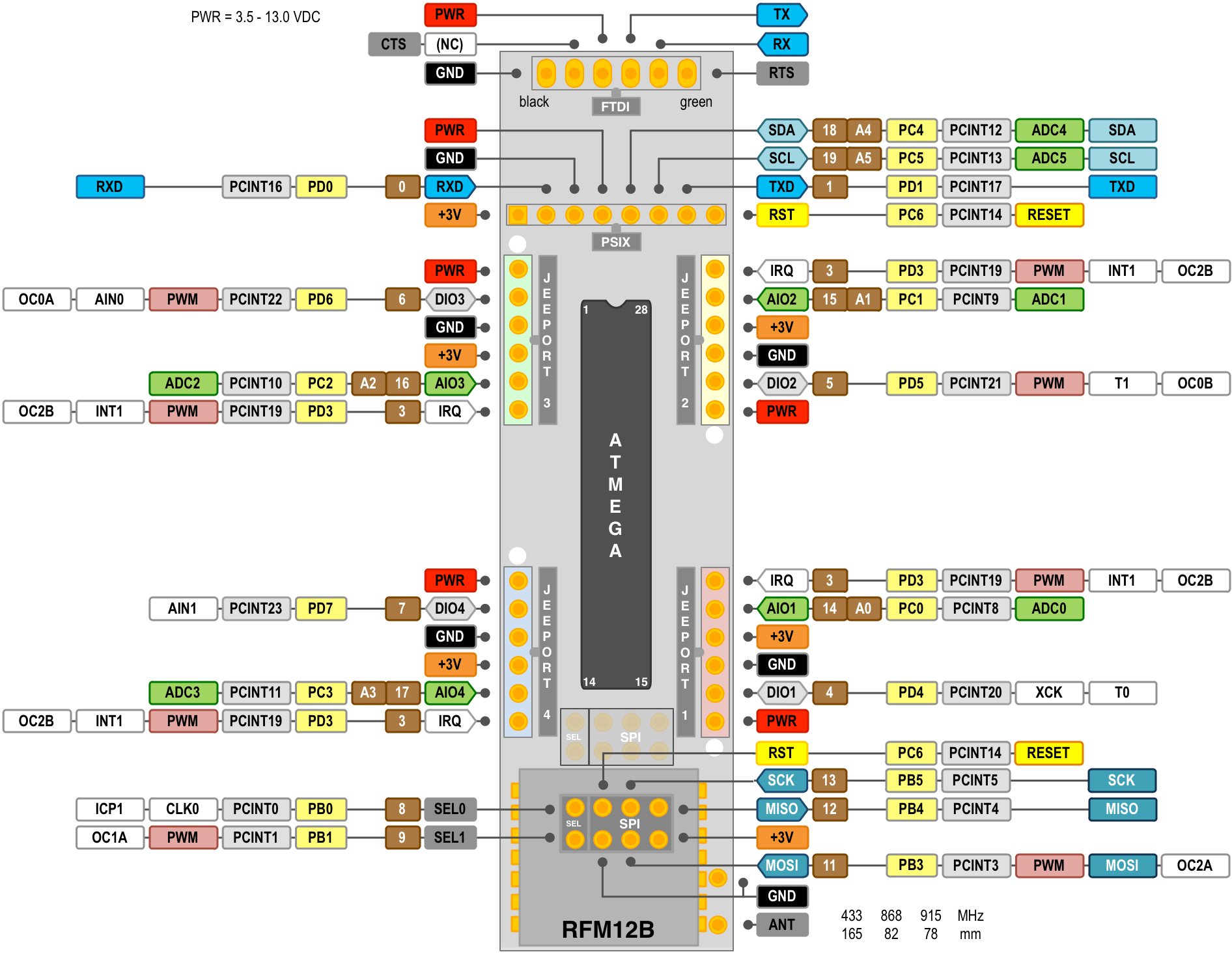
What I picked instead is a JeeNode board, without its wireless transmitter (which is too expensive for my taste). This board is Arduino compatible, designed for battery operation, there’s a (single-man ?) company behind it so the boards are available commercially, and there’s a rich wiki and a lot of documentation available over at JeeLabs. This weblog is no longer updated but it contains a lot of useful information and I strongly advise you to go through it.

Pulse counting
We want to transmit every pulse we receive to the Raspberry Pi. What if it’s currently powered down? What if our wireless packet wasn’t properly received? Transmitting every single pulse is certainly a good idea, but we can do better at no extra cost, since we’re buying a microcontroller anyway: count the pulses, and transmit the count (at every pulse) to the server. The server will subtract the old value from the new value, to find out how many pulses have happened since the last packet - typically one. This way the server will never miss pulses (if it missed a packet, it will see that two pulses happened since the last, and our data is reliable even with packet losses, which happen a lot in wireless), and if it’s powered down for some reason, when it goes back up, it will catch up automatically. Counting pulses is just incrementing a counter, which a microcontroller that does SPI can do without a problem.
Batteries
This system is going to run on batteries. I have a bunch of AA alkaline batteries, as well as AA rechargeable batteries. The rechargeables are essentially worthless and have 48h of charge retention - but I didn’t know that originally, and it’s after buying low self discharge Sanyo Eneloop batteries that I realized the technology was fine, it was just my batteries that were dead). I also have some 9V batteries lying around. What we need is to feed at least 3.3V to the JeeNode and the nRF24L01+. We can achieve that with 3 alkaline (4.5V) or 4 NiMH (4.8V). 3 NiMH might work too, I don’t remember if I tested it. (I think such a low supply voltage works fine for the JeeNode, but not for the tranmsitter that becomes unable to transmit.) So I bought a 4-AA battery case with leads and a switch, and have populated it with 3 supposedly dead alkaline batteries. Then rechargeables, when the alkalines were truly dead.
Case
The system needs to go in a case, especially since it’s going to sit outside of the house, and therefore may be touched by neighbors. Security is important (although this kind of circuit is very low risk), short circuits must be avoided as usual. I didn’t bother putting a fuse, however. Since I have a separate battery case (because placing battery clips in another case is very difficult and I don’t like to waste time on this), the system will have two cases. You have to adapt to the cases available on the market.
3-Receiving data on the server
We picked a nRF24L01+ transmitter on the JeeNode, naturally we need the same on the other side. How to make it interact with the Raspberry Pi? It turns out that the Pi has a SPI interface, so it’s just a matter of plugging it correctly… and then deal with the mess that the software side is, which I’ll cover later.
All you need here are a few wires to hook up the transmitter to the right pins on the Pi.
Hardware implementation and BOM
Custom reed sensor
BOM
- reed switches, small if possible, buy 10 if possible
- some foam (optional) to cushion the reed switch
- a piece of veroboard, a saw or a drill with a small bit
- a LED and its protection resistor
- one pullup resistor (47 kOhm)
- 3 pin male header for connection
Assembly
The sensor will have three pins: +5V, OUT, and GND. A resistor will pull OUT to +5V by default, and the reed will close a connection between OUT and GND, thereby sending the microcontroller a 1 in steady state, and a 0 on a pulse (which, by the way, goes from digit 9 to digit 1 on my meter).
Hook everything up so that the reed switch gets below the “liter” wheel, in the small compartment. It has to touch the plasting casing of the meter, in my experience, but be careful not to push too hard because the glass will break very easily. Don’t bend the pins of the reed switch: instead, solder wires at a 90° angle. You’ll break a few switches, that’s why I made you buy several.
Be absolutely sure to wire up a LED (with its resistor) to the sensor, so that it lights up when a pulse is detected. You will need it to accurately position your sensor. As you can see on the pictures, I’ve hooked mine up with adhesive putty. It’s strong enough and hasn’t moved in months, but the original placement required me to cut the gas while the displayed digit was 0, and move the sensor so that the LED would be lit. Had I added a LED in the beginning I would have saved two hours sitting outside in front of the gas meter, in flip flops and pajamas, trying to place the sensor while a relative was having a shower.
Major lesson there folks: diagnostic LEDs are important. Use them. (I may have been a little too ambitious with 3 diagnostic LEDs hooked up to the microcontroller - but I ran is serious wireless issues which were hard to debug.)
Below is a picture of my sensor, stuck in place by a lot of adhesive putty. Sorry, I didn’t take it off for pictures - placement is annoying to do. (For what it’s worth, it hasn’t moved in months.)
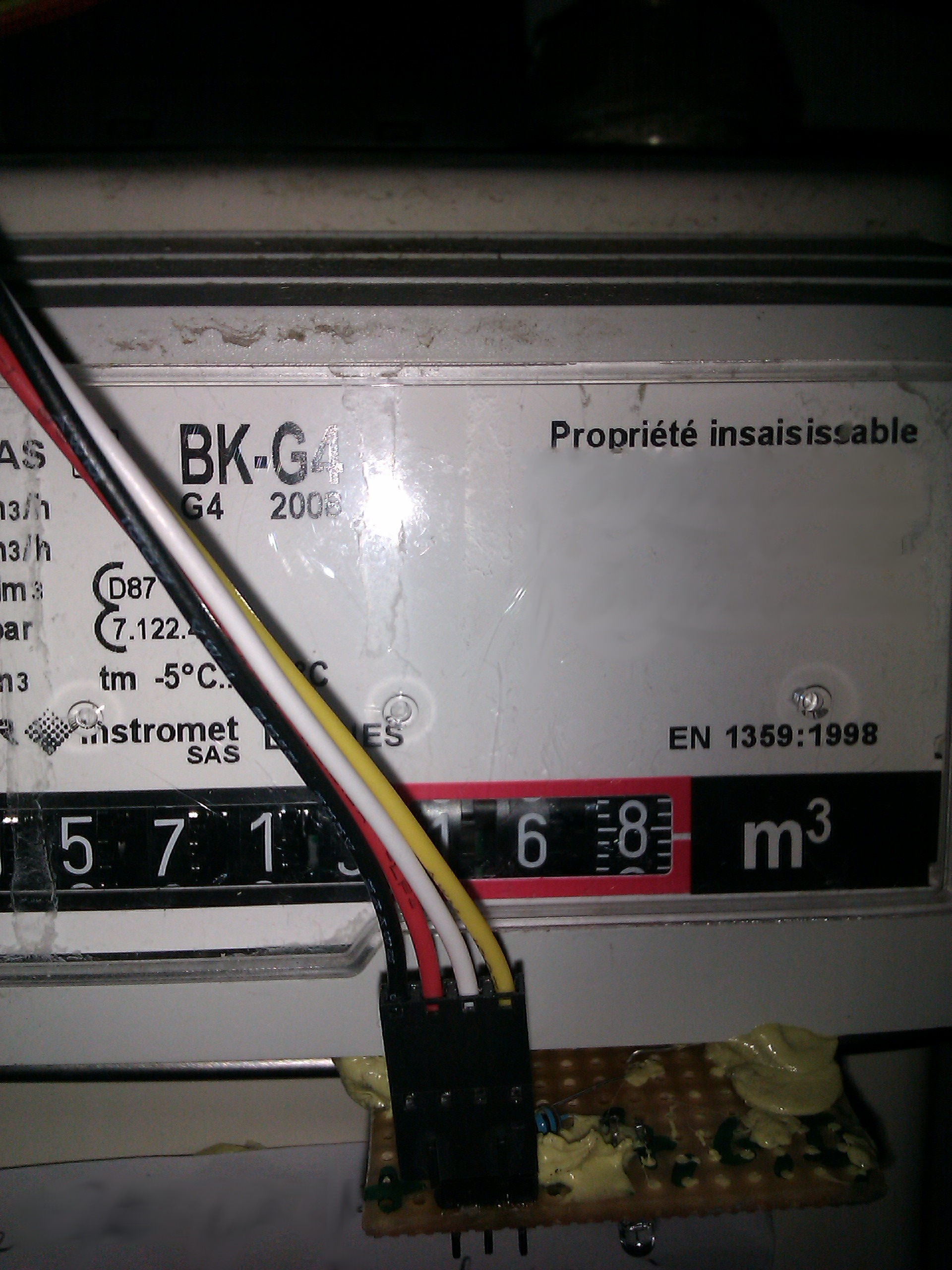
On the picture you can see: the diagnostic LED (it’s just about to light up, because the liter wheel shows almost 9), the pullup resistor, and the 4 pin cable (of which only three pins are connected). Not seen is the reed switch, on the underside of the meter.
Update in January 2015: I was tired of the homemade sensor and wanted to buy something that would be mechanically more resistant. I purchased a door-opened sensor, that has the advantage of coming in a plastic casing. This is what it looks like:

Microcontroller, wireless transmitter
BOM
- jeenode v6, no RF http://www.digitalsmarties.net/products/jeenode 14 EUR
- nRF24L01+ module http://yourduino.com/sunshop2/index.php?l=product_detail&p=188
- female header http://dx.com/p/diy-parts-2-x-4-pin-female-headers-10-piece-pack-136762
Assembling
Assemble the JeeNode kit as documented, this is not hard at all. Add the female header on the SPI slot (note: you may also solder actual wires there - up to you. I might solder wires instead if I did it again).
Be very careful on the pinout : first of all, the pinout of the RF24 module and that of the JeeNode SPI are not the same, so you can’t do a straight connection. Refer to the JeeNode wiki page for the pinout, and be careful about the nice looking graph that they have, because it swapped RST and SCK (I’ve fixed that for you below, after wasting three hours on the matter).
I haven’t taken the picture of the elements outside of the case.
Case and LEDs
BOM
- project box of the right size. I bought the following: http://www.ebay.com/itm/2pcs-NWE-Plastic-Electronics-Project-Box-Enclosure-DIY-27x60x100mm-construction-/151085140096
- LED kit, resistor kit from DealExtreme http://dx.com
- drill with large & small bits, or soldering iron to melt the plastic
- hot glue gun (optional)
Assembling
The case is small, perhaps a little too small. I had to mill the four plastic supports inside, and create holes for the battery connector, connector to the sensor, as well as an external reset switch (used for programming and rebooting), three diagnostic LEDs, and the FTDI connector. That way I never have to open the box again ! Use a drill or soldering iron to create holes for the various connectors, and hold them in place with hot glue. Cyanoacrylate is supposed to be great but I found it’s not as strong as it pretends to be (except on skin).
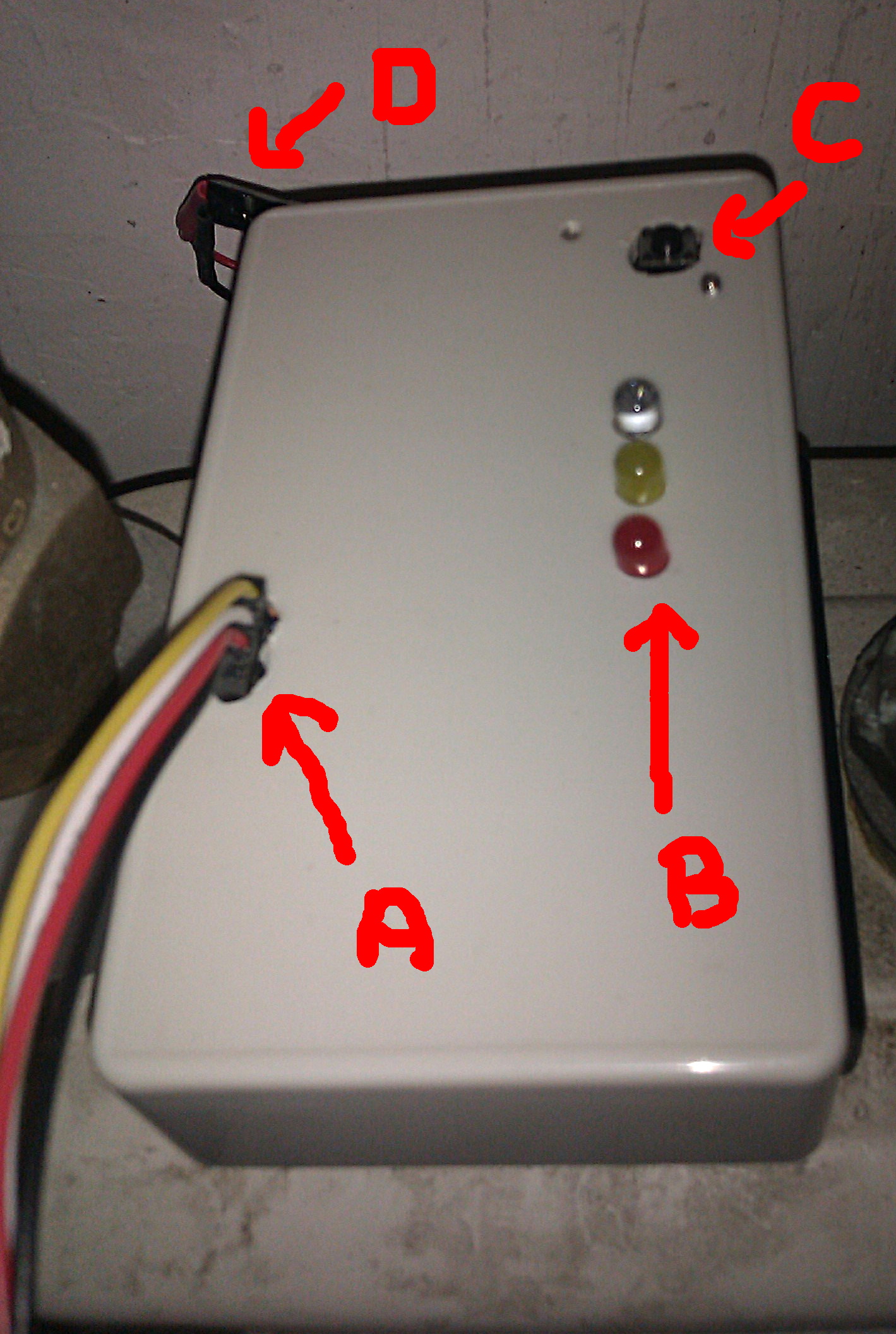
On the picture I’ve identified the following elements:
- A is the cable connecting the sensor
- B are the three diagnostic LEDs (used to show the wireless transmitter state when transmitting, normally off to reduce power consumption)”
- C is the reset switch
- D is the battery connector

Raspberry Pi
Hook up your transmitter (be careful of the pinout) to the Pi. You should use the standard SPI pinout, although bit-banging on the GPIO is probably not less reliable than what I ended up with. I initially suspected the wiring, but I’m now almost certain that the software is responsible for the relative lack of reliability that I was observing initially.
Software
There are three pieces of software.
1-On the JeeNode
The code on the JeeNode has the following responsibilities:
- receive the pulses from my reed switch sensor and accumulate them
- transmit pulse count over radio to the Raspberry Pi
2-On the Raspberry Pi
The code on the Raspberry Pi does the following:
- receive the pulse count from the JeeNode
- report the pulse count to a web-based application for storage and graphing
It does not store data or generate graphs, this is taken care of by a separate computer to which the Pi sends data over wifi. The Pi is not a powerful enough computer for certain things, and I already have an eeePC set up for various other tasks. You do this, by the way, with http://dx.com/p/mini-usb-2-4ghz-150mbps-802-11b-g-n-wifi-wireless-network-card-adapter-black-120933 (unfortunately sold out as of this writing). Luckily, Linux has gotten to a point where USB controllers and wifi controllers almost all work out of the box (unlike on Windows 7 where some of them require separate drivers to be installed), and this dongle just worked without my doing anything.
Why, then, do I not have the eeePC receive pulses directly from the JeeNode, instead of going through this intermediary? The eeePC is a computer with USB interfaces for I/O and that is it. How am I supposed to get a SPI-based wireless chip to work on that? I could buy a USB<->SPI chip, but I don’t know if this exists at all, and I have a Pi anyway which has a SPI interface already.
Receive pulse
We need software that is able to drive the RF24 transmitter on the SPI bus. It is a good idea to try and use the native SPI support in the kernel. Using /dev/spidev0 then allows you to write a driver with more ease. I actually didn’t write the driver, but grabbed a port of maniacbug’s RF24 lib to Raspberry Pi, done by stanleyseow
I’m seriously unimpressed with both the Linux kernel support for SPI on Raspberry Pi (upgrade it and it breaks! so much for the Linux policy of never breaking userspace) and the driver itself. Both would need more work but I haven’t looked into it yet.
Bit-banging on the GPIO is another option, but it sounds hard to get it right so I’d stay away from that.
Once we have a basic driver, we need a piece of software that receives the pulses. Mine can be found at https://github.com/sven337/home-monitoring-client/blob/master/gas/ - it’s a very simple program based on the examples from the RF24 lib I’ve decided to use.
Report pulse
To make things easy I’ve decided that the server would be a web application, that exposes a few services with Flask. So pulse reporting is simply a HTTP GET request done with curl. A single line takes care of it.
WiFi reliability
A bit off-topic - the WiFi interface, being cheap, is somewhat unreliable, which doesn’t matter all that much given that we send about 5 packets every minute, and they’re not critical in the first place. Still, I have a script that periodically checks if the interface or the network went down, and electrically disconnects and reconnects the dongle to restore everything. It works beautifully, and I can take out the dongle or disable the wifi for whatever reason, everything comes back up automatically without me having to log on to the Pi - which I can only do over WiFi anyway. See https://github.com/sven337/home-monitoring-client/blob/master/data/check_wlan0.sh for details.
3-On the web server
A separate web server, which happens to run on a eeePC 701, receives the information from the Raspberry Pi, stores it, generates graphs, serves them over the web, makes coffee and ratatouille. Only part of it (data service and storage) is online, I will add the graphing part soon enough.
I used Flask to provide a few web services used by the Raspberry Pi: send gas pulses, update electricity meter data, and update temperature.
The data is then fed into rrdtool, a good tool for storing this kind of data. Using MySQL or any similar DB is a bad choice, because it’s going to be slow, and grow over time to large sizes for no reason. Do you really need 5 minute temperature data from five years ago?
rrdtool is also a bad choice, for other reasons that I found out about later, and will elaborate upon in a forthcoming article detailing the web part of my home monitoring setup.
Feedback and lessons learned
The system has been running on salvaged alkaline batteries for about six months, and it works well. Positioning the sensor correctly took a lot of time, as well as programming the transmitter correctly so it wouldn’t lock up. This beast is fairly sensitive and the RF24 library (on both sides) can easily lock it up if you’re not careful. My programs work, but any particular way of using the RF24 API is not guaranteed to. Interrupts from this transmitter module are unreliable, so is the automatic retransmission system, and the low power mode of the microcontroller (which is absolutely necessary if you want good battery life) tends to interact with the transmitter. Be very sure that your transmission is done before you shut down the microcontroller or chaos will ensue. Diagnostic LEDs are really important. Design with them upfront, you’ll save a lot of time. Retrofitting a tightly integrated device to accomodate new LEDs is not fun, and debugging a microcontroller program without any actual output is very hard as well. :)
Packet loss is about 10%, not a problem at all. Battery life is great: I’ve changed batteries twice but they were supposedly dead alkalines. With high quality NiMH this device will have about a year of autonomy. You can’t really ask for more for a wireless device!
The Raspberry Pi’s side is still brittle. I haven’t properly encased the wireless transmitter, so it hangs by its connecting wires next to the Pi. Touch the wires and the chip will lock up, requiring a restart of the receive program. Upgrade the kernel and spidev0 will completely disappear. This is annoying because about once a month, this part of the system requires attention, and this is not what I wish. Future work will focus on physically “cleaning up” this part (putting the transmitter in a box), and ensuring that the software works well, which isn’t really the case at this point. Update: I’ve moved to using librf24-bcm instead of GPIO-based SPI, and it’s significantly more reliable. I’ve also slightly improved the wiring, even though the Pi and transmitter are not in a box, and it helps.
The graphs let me see quite a bit about when my central heating is running or not, how much it really consumes, and how much gas we burn doing the dishes and taking showers - although this is harder to see because reading pulses is inherently “spiky” and imprecise - you never know when you’re not consuming gas. First part in changing something is measuring it, and once we also see water consumption we’ll have a clear view of how much our bathroom habits cost. Then we can try to change them.