I bought a cheap LED strip amplifier on eBay. It is supposed to be used to build long LED strips: due to the resistivity of the copper tracks on a strip, you can’t really plug more than 5 to 10 meters of strip to a single power supply without experiencing color fading, or thermal issues. The amplifier is supposed to be interposed between strips, and it will allow you to chain as many strips as you like in a row. Of course, the amplifier has a power input, so you need an extra power supply.
Using it as a LED strip driver
Anyway, my objective is to use this item as a driver, with the input being an Arduino-style microcontroller. An Arduino can’t drive a strip directly: you need one MOSFET per color. That’s very easy to set up, but what you will do by yourself may not be as physically compact (nor as cheap…) as this item!
Teardown
So let’s see how this “amplifier” is designed and what we can do with it.
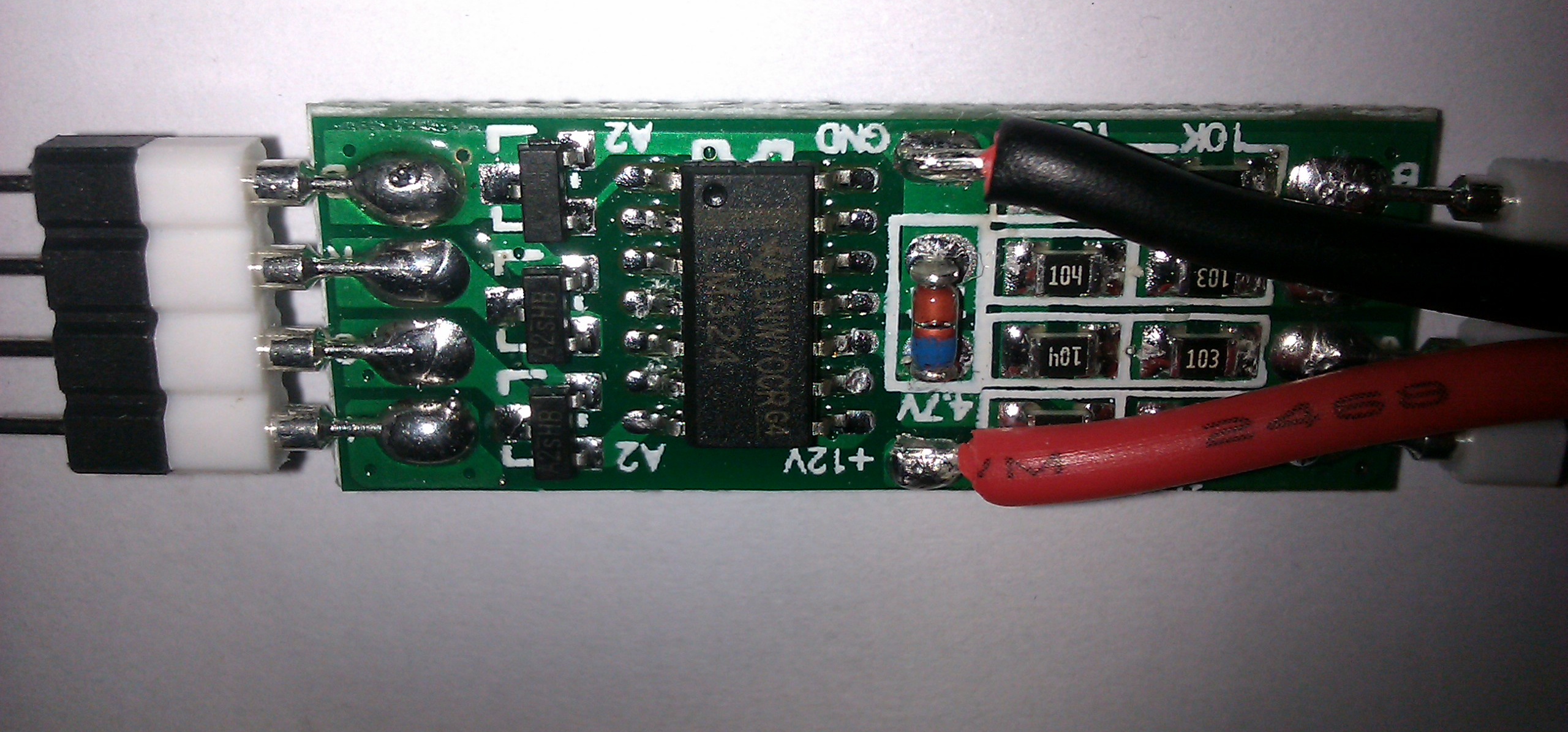
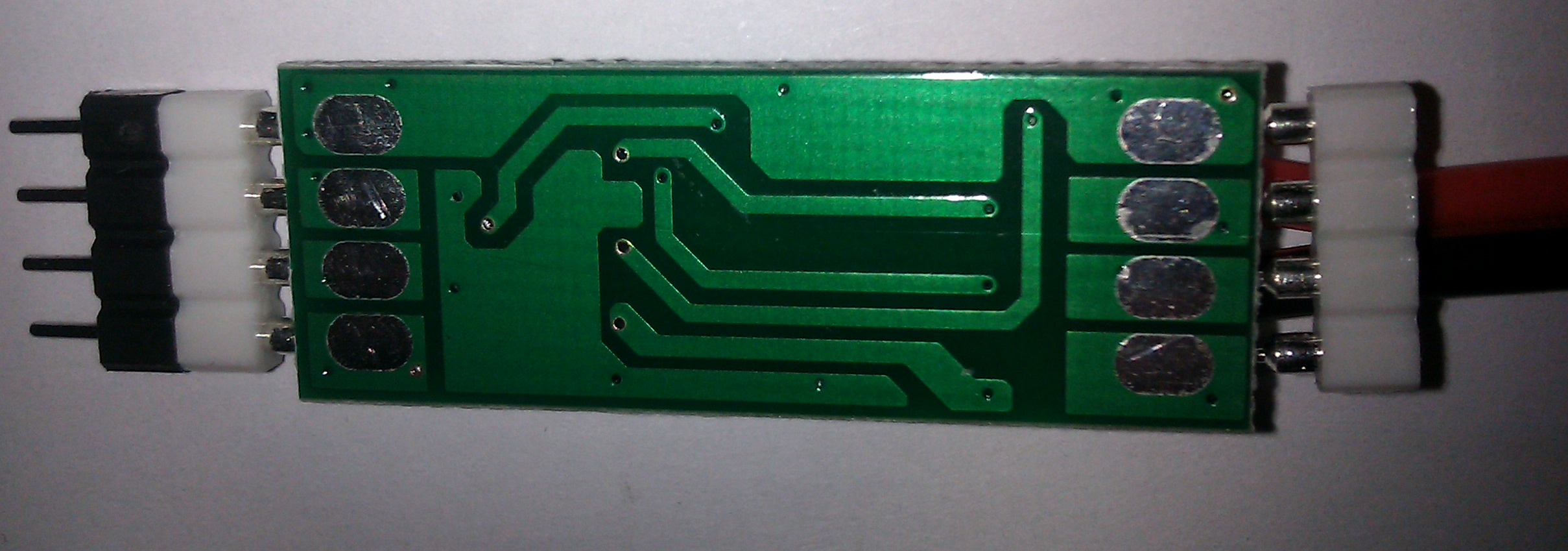
The item is a bare PCB protected by a white heat-shrink tubing, with a label attached that indicates where the input and output are (they are not interchangeable, of course). I know that my pictures aren’t great, I am in the process of buying a real camera, which should help in future articles. :)


Design
Power stage
We see three transistors. They are Si2302 N-MOSFETs, and they’re used to switch power on the output side. A quick look at the datasheet shows that they are rated for a maximum of 2.8A, a far cry from the advertised 4A on the label (and 3A in the eBay item description). And even 2.8A will be difficult to maintain for a long time, because of thermal constraints. As a result this amplifier is only good for about 2A on each channel, in other words a total of 6A which more or less matches the real current consumed by 5 meters of a made-in-China 5050 RGB LED strip. (Officially they’re said to consume 1.2A/m, in reality it is a bit less.) Don’t use it for higher currents, as the transistors will overheat.
Logic
The transistor’s gates are connected to the outputs of a LM324 quadruple operational amplifier. The fourth amplifier on the chip isn’t used, since there are only three channels (R G and B). It’s interesting that the chinese designers picked an operational amplifier for the task: a comparator or even a simple CMOS inverter would have sufficed.
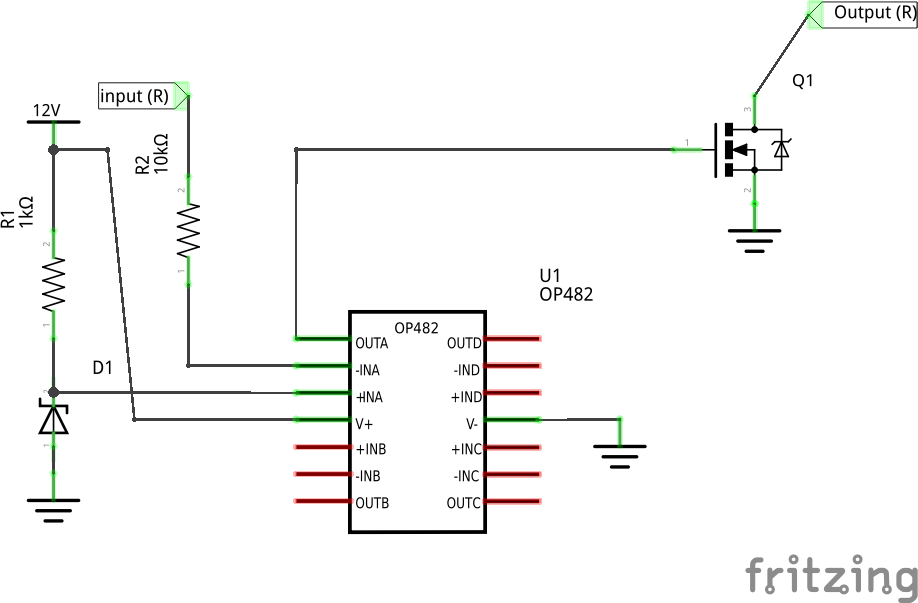
The amplifier appears to be wired as an “inverting comparator” : the positive input is fed 4.7V from the Zener on the PCB, while the negative input is tied to the input pins of the device. As a result, any signal on the input pin that is lower than 4.7V will translate as a logical 1 on the output of the amplifier - and will therefore turn on the corresponding MOSFET, lighting the LED; while signals higher than 4.7V will translate as logical 0 and will turn off the MOSFET.
If you’re wondering why the inverting behavior, it actually makes sense when you consider the original use case this circuit was designed for: it’s meant to interpose between LED strips. Most LED strips are designed with a common +, in such a way that the - for each color can be hooked up directly to an N-MOSFET (the cheaper/most common kind). In this situation, you light up the LEDs by connecting the color pin to ground - which is a logical zero; and you stop the light by connecting the color pin to a voltage level higher than, or equal to, the positive supply (generally +12V). Logically this second step translates as a 1.
So the job for this amplifier is to turn a “1” at input into a “0” at the output, and vice versa, while of course not consuming power on the input, but on the power pins (that’s what an amplifier does). That’s why it is designed this way. Note that the operational amplifier doesn’t really amplify anything here, as it’s used as a comparator. The MOSFETs are doing the amplification.
Below is what I think is a rough schematic of how it works (R channel only, as I really don’t like working with Fritzing and don’t know anything better) :
Use as a driver
It seems that this circuit (which I haven’t tested yet, so far I’ve simply torn it down!) would be a decent LED strip driver for currents of up to 6A (which roughly corresponds to 5 meters of 5050 RGB LEDs). There’s just one caveat: the inverting behavior of this circuit means that you’ll have to invert the outputs on the Arduino, as compared to what would be intuitively correct, to get the result you want. In other words the PWM value has to be complemented: if you wanted to write a 0 (complete black), write 255. If you wanted to write 10, write 245, and so on.