I bought a brand-new, expensive vibro, but it would usually not turn on after pressing the ON button, unless you tried to charge it. If you try to charge it it will usually do nothing, but once every ~40 attempts, the LED will light up, and at that point the device is “awake”. If you then disconnect the charger, you can use the device successfully, but if you leave the device alone for ~30minutes, then it will go back to this unwakeable-sleep. This is near unusable, and I got a refund from the reseller. Supposedly the whole batch was problematic so they didn’t replace it. This is the first time I bought a commercial product from a European reseller that straight up doesn’t work.
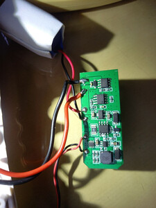
Still, it was usable with a bit of fiddling… but after a while, it refused to start at all, even when its LED was on, so I had to open it to see what was wrong. The answer is “many things”, and this article covers the work done to recover a mostly-working vibro wand.
The motor breaks
The issue that led it to not starting at all was that the motor was damaged. It uses a DC motor, and when I put 8V across it it wouldn’t move, while drawing 3W. Opening up the motor, the brushes weren’t touching the collector any longer, but were resting on the shaft. I managed to reshape the plastic holding the brushes, and that fixed the issue.
These DC motors are crimped shut, so once opened they are difficult to properly close again, but thankfully I had prior experience with that. I was able to save the motor, which is good because it was a beefy one. In this device, the DC motor housed is in the body rather than the head. The vibration is transmitted through a spring mechanism to weighted elements in the head, providing more effective vibration than typical small wands where the motor sits directly in the head. This justifies the price of ~75€ instead of the usual 15€ from Aliexpress.
The original issue persists
But of course, the original issue persists. If you can get the device to start charging, then you’re good and everything will work, but plugging in a charger usually does not work, and pressing the ON button without plugging in a charger never works at all. This is strange behavior, so let’s look into it. Thankfully this device is pretty easy to open, some of the silicone is glued but the disassembly process is largely non destructive and fairly simple. I’ve known devices where removing the silicone sleeve would take 30 minutes.
Hardware Architecture
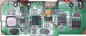
The electronic architecture consists of several key components:
- A SinoMCU MC30P6280 8-pin microcontroller
- A XT9502 2S lithium charging chip
- A 7533 linear voltage regulator, pinout is GND/Vin/Vout
- A MOSFET for motor control, I was unable to find the model or datasheet but the pinout is obvious
- A custom boost circuit for the charging_
- 3 buttons and 2 (in parallel) LEDs for status reporting
Here is an annotated picture:
Design flaws
Missing capacitors
Both the charging circuit and the linear regulator’s datasheets call for 10µF capacitors, but these were nowhere to be found, only tiny ceramics. That must not help with stability which can well be causing the sort of intermittent issue the device is showing. The picture shows a tantalum capacitor that I added, I also added bigger decoupling caps.
I felt the motor could also use a large cap across its terminals so I added an electrolytic, verification on the oscilloscope showed a much nicer curve and lower noise on the power supply while the motor was running. Note that this is likely not related to our problem since it happens before the motor is running, but it’s not impossible that starting the motor for the first time creates a large enough transient that immediately kills the MCU before one even feels the motor move. In fact, I have observed a few cases where the motor starts, runs for a second, and then the device stops, which is consistent with the idea that electrical noise from the motor is freezing the MCU.
Root cause hypothesis: electrical noise?
Long story short, I haven’t been able to definitely fix the problem, but it does feel like a marginal condition either on the power supply or on one of the pins of the MCU.
The MCUs pins are:
       _____
Vcc   -|1  8|- GND
MOTOR -|2  7|- Bpwr
LED   -|3  6|- B+
RST   -|4  5|- B-
       ‾‾‾‾‾
Bpwr, the power button, is connected through a weird resistor voltage divider, so it floats at 2.9V (which is still a 1). I do not understand why, possibly some strapping value at boot time, but the (Chinese-only, the copy I linked above is Google translated) datasheet doesn’t describe this at all. There could be something wrong there, actually, especially as this is also used as an interrupt pin.
The LED is shared with the XT9502: both chips can drive it. RST is used by the XT9502 to inhibit the motor while the battery is charging (no great reason why, but given how the inductor on the boost circuit heats up in normal charge, I can imagine it would burn up if one was drawing more current).
With the added capacitors, I see the issue less often, but still sometimes, which does suggest that the problem was/is indeed an electrical noise issue. Sadly there’s only so much I can do and maybe replacing the MCU will actually help, if the replacement is less “touchy”.
Root cause hypothesis: buggy FW or broken MCU?
In addition to the electrical noise hypothesis, one can also wonder if the problem doesn’t lie within the MCU, either as a firmware bug, or just a broken MCU. Given the datasheet, it sounds like this device is a clone or imitation of a PIC12C508 MCU. This is a one-time-programmable chip, which sucks.
My next step is to replace the MCU with a pin-compatible 8pin MCU, so that I can hopefully fix the problems and make some UI improvements while I am at it. UI improvements would be:
- instant-on instead of having to press for 5 seconds (an eternity in some circumstances)
- a wider range of speed settings
- different/custom vibrations
- no wifi/bluetooth because that’s not terribly useful
Replacing the MCU altogether
I have better behavior now, the device turns on successfully about 50% of the time, up from 0%. But this isn’t 100%, so I am not satisfied. The MCU replacement comes next.
I would honestly have saved more time re-doing the entire board from scratch or at least replacing the MCU from the start, instead of trying to reverse engineer their design and figure out what is wrong. It turns out, the firmware was wrong - after hooking up the oscilloscope I could see the MCU driving (as output) the pin normally used for power button input, unless some magic/luck is happening, and I think this is the core of the issue.
I bit the bullet and replaced the MCU with an Arduino Pro Mini, using 30AWG wire wrapping wire to connect it in the spot of the SOIC8 MCU. This was not very easy but it worked. In my testing I killed the MOSFET so I replaced it with a FDS6690A I had lying around. This took but a few hours. The code for the custom vibro firmware is on my Github as always.
Custom vibro firmware
This custom firmware has the UI improvements that I needed, namely: start right away on a power button press, ramp speed up and down on long presses, plus custom vibration modes tailored to personal tastes established after a rigorous evaluation process.

