First of all, a disclaimer: this project runs on mains. So for most closets, where no electricity is available, it won’t really work. With that bit of awesomeness out of the way, let’s see how to build the simplest, cheapest automated lighting for use in a closet, cabinet, …
Objective
We build a closet under our stairs. It’s closed with curtains, and we need artificial lighting in there if we want to see anything. Luckily, a mains socket is available in this closet, which will simplify the design.
So here’s what we need:
- sufficient light output for a 2 square meter storage area full of different things
- cheap solution
- automatically lights the closet when somebody opens the door/curtain
Let me show you how I achieved it.
Hardware
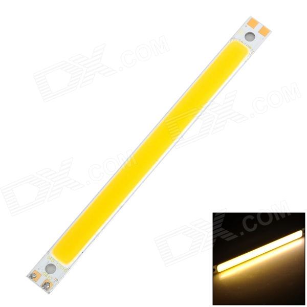
I decided to try a COB LED bar. These are (fairly) high-powered LEDs in the form of a metal bar that is about 15 cm x 1 cm. It looks like it will be easy to attach inside of the closet.
The LED needs a driver (if you connect it to the power supply directly, you risk overdriving it and killing it quickly, not to mention the dangers of producing a - localized - lot of heat in a closet), so we’ll buy a ready-made one. I had a 14V 400mA power supply, salvaged from an old epilator (not mine!).
BOM
Here is what I used:
| Part | Link | Cost | |
| 4W COB LED stick | http://www.dx.com/p/0412-12010-4w-350lm-3300k-cob-led-warm-white-light-stick-white-yellow-223799 | 2.80USD | |
| MR16 4W LED constant current driver | http://www.dx.com/p/4w-led-constant-current-source-power-supply-driver-8-12v-197205 | 1.75USD | |
| Passive infrared sensor | http://www.ebay.com/itm/400330055400 | 1.90USD | |
| Power supply | salvaged | 0USD | |
| 12V jack connectors | http://www.ebay.com/itm/321088164543 | 2.70USD | |
| KF2510-2P connectors | http://www.ebay.com/itm/370696057892 | 1.35USD | |
| FDS6690A transistors | Ebay (seller disappeared) | 3USD | |
| Total of required parts | 13.50USD |
Design
There are very few components so this is a simple project. However, it still requires a little bit of skill with a soldering iron. The general idea is for the PIR sensor to turn the LED driver on and off, thereby switching the light on and off. What’s interesting is that there are many cheap, 3-5W LED drivers in a MR16 form factor, just like the one I picked. The PCB is similar between these different drivers, but the components onboard may actually differ quite a bit. The controlling IC is always a buck converter, but the exact model of IC chosen will depend on which Chinese plant the device comes from (or something like this).
An extra transistor is needed
I bought a driver like this for my LED lamp, and it was using a PT4115 chip. The huge advantage of this chip is that it had a DIM pin, which was basically a logic-level, PWM-ready input pin: in other words one could hook it up directly to any sensor or microcontroller. Of course this required soldering a wire to the tiny, tiny pin, but this wasn’t as hard as it seemed. Unfortunately the particular model of driver that I received is based on a different chip - I forgot to take note of its reference, and this isn’t happening now that the driver is thoroughly coated in hot glue - and it doesn’t have a DIM pin.
This means that the PIR sensor cannot be connected to the driver directly: we’ll instead use it to switch power to the driver, with a suitably chosen transistor. Of course the output of the PIR sensor cannot be used as the ‘+’ input of the driver, because its current output capability is ridiculously low (as is normal for a logic pin). Any transistor that has a ~3.3V threshold voltage, can isolate 15V or more, and can tolerate at least 1A continuously, will do. I happen to have these FDS6690 transistors lying around: they’re SOIC, in other words surface mounted devices (SMD). Most transistors for amateur electronics use a through-hole format such as TO-92, but I find that SMDs can be equally easy, if not more, to solder, and they occupy less space which makes them easier to integrate.
Modding the driver
The LED driver I chose is designed for a specific use case of replacing a 12V AC halogen lamp with a LED. This kind of halogen bulb is commonly used in kitchen and bathrooms for low-power, small footprint needs. The lamps are these small bulbs with two prongs (MR-16 form factor), and pull about 10 watts of power each (which is a lot). They are generally driven by a 230V->12V transformer (a mere transformer, so it outputs AC).
Anyway, there appears to be lots of cheap MR-16 LED drivers, which is why we picked one - but the use case they are designed for doesn’t have much to do with ours! So what differs?
- we don’t use MR-16 input
- the small form factor isn’t a hard requirement in our case
- we provide direct current (DC), not AC as the driver is designed to accept
- we need an extra transistor, as explained before
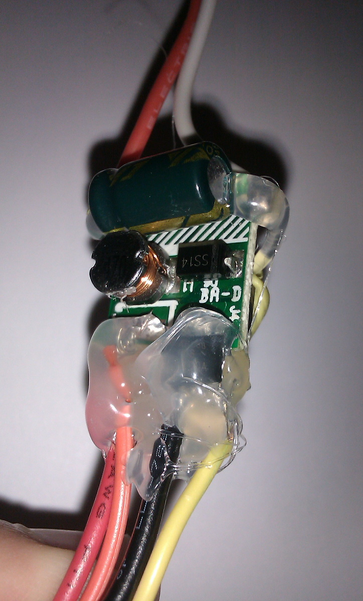
So the driver needs to be modded a little bit. First of all, we’ll eliminate the input pins. We don’t need these, and we’ll solder wires - but later on. For now just remove the input pins. Then, there’s the input stage of the driver that handles AC, that can be removed. It’s made of four diodes (the black squares marked SS-21) and a capacitor, providing the onboard IC with direct current. This stage is useless since we’re giving DC, although it doesn’t really hurt anything apart from efficiency. In my case, the power supply has a voltage that is somewhat too high (14V instead of 12V), so I decided to keep this input stage. I don’t care much about the voltage drop from the diodes. If you do, remove them. Removing the capacitor has no real advantage (its ESR is normally low enough that it doesn’t significantly reduce efficiency), so unless you’re running battery-powered, you can leave it. Note: don’t remove the fifth diode, which is part of the buck circuit and definitely a needed element of the driver! Lastly, there’s the transistor we talked about that needs to be added, and here the fact that it’s an SMD transistor will actually make things easier. Remember that an N MOSFET needs to be on the low side, that is to say, it must be located between the load and ground. If you do it the other way around it won’t work - and a P MOSFET behaves the opposite. If you don’t know why we can get into it but there are resources online that cover this well enough that I’ll just move on. Here, the load is the driver itself (with the LED connected at its output). The transistor needs to be located between the driver and the minus pin. In other words, the positive lead from the power supply will be connected directly to the driver, but the negative lead will be connected to the transistor instead. The gate of the transistor goes to the output of the PIR sensor, the drain (where the electrons are drained = positive) goes to the driver’s negative pin, and the source goes to the power supply’s negative lead. So solder the 3 drain pins directly onto the spot where the minus input pin was previously soldered (and that’s we didn’t install the wires right away!) - this is the easy part. Solder a wire to the gate pin, to go to the sensor output - this requires good coordination. Solder a wire to the source pins, it will go to the power supply negative lead.
Once this is done, the driver is ready, but physically pretty weak. Give it a good coating of hot glue to secure the leads and the transistor to the board. While you’re at it, I advise glueing a small piece of velcro too, so later you can attach the driver to whatever surface you want with velcro, instead of resorting to adhesive putty (which doesn’t hold really well when the driver heats, as I found out later).
This general principle of adding a transistor and a cheap PIR sensor is useful for many lighting projects.
Pictures
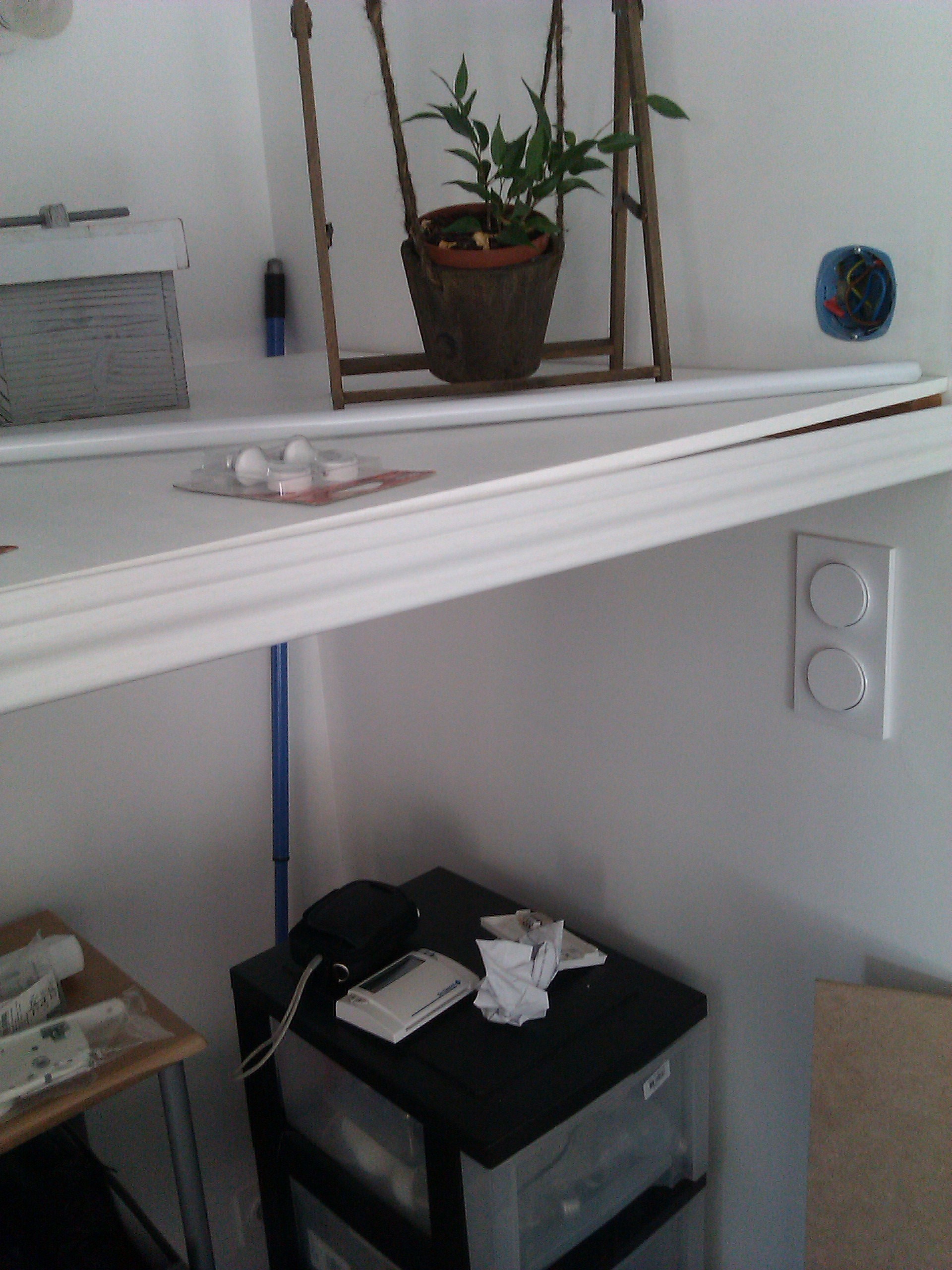
This shows the closet being constructed, with no inside lighting.
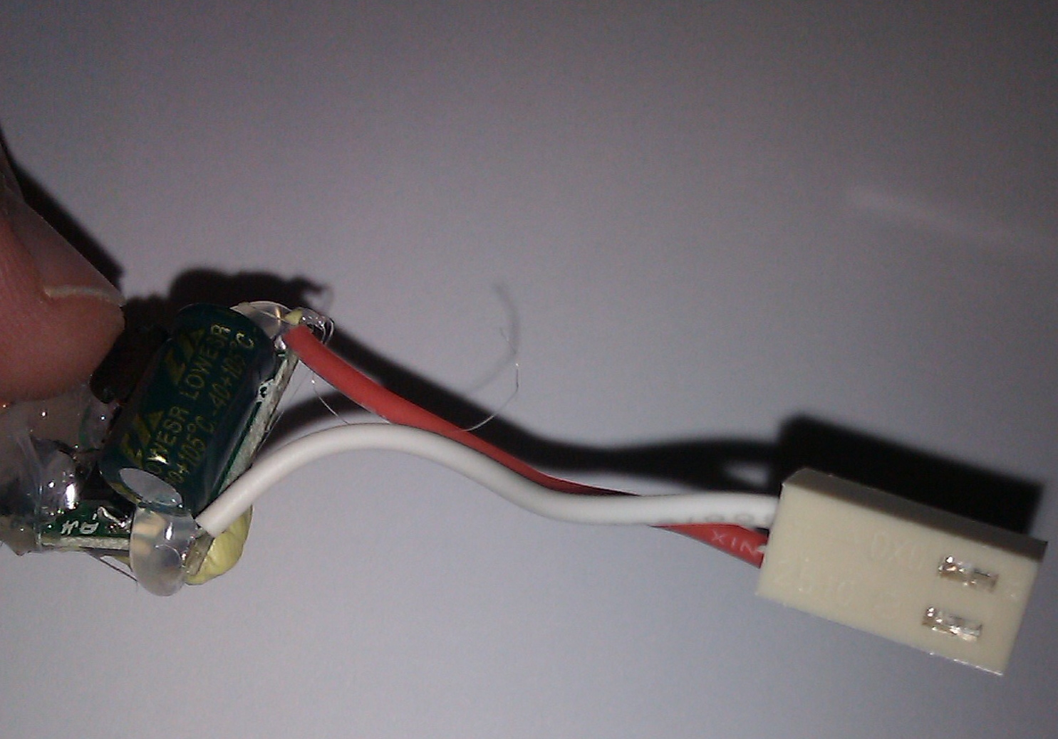
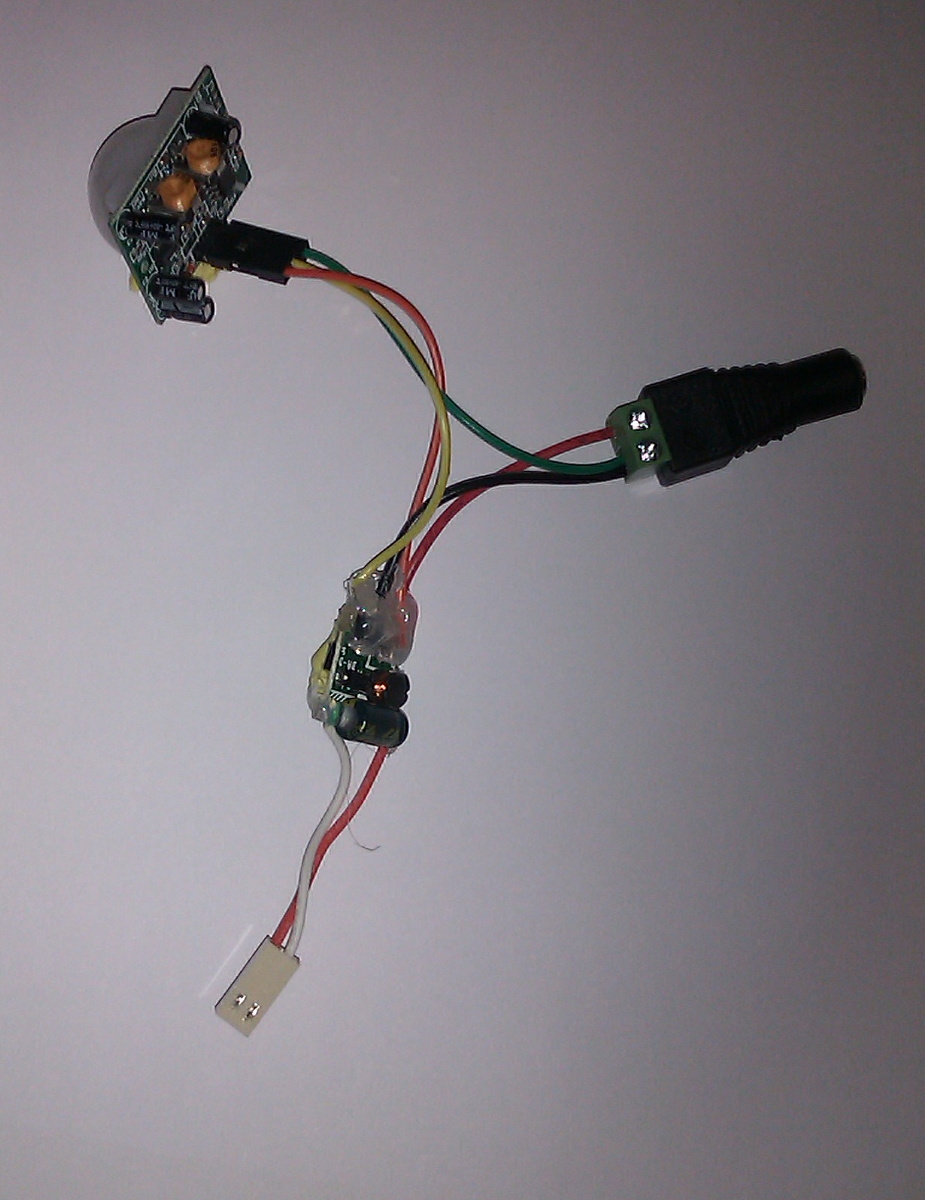
The system, ready for installation, looks as follows:
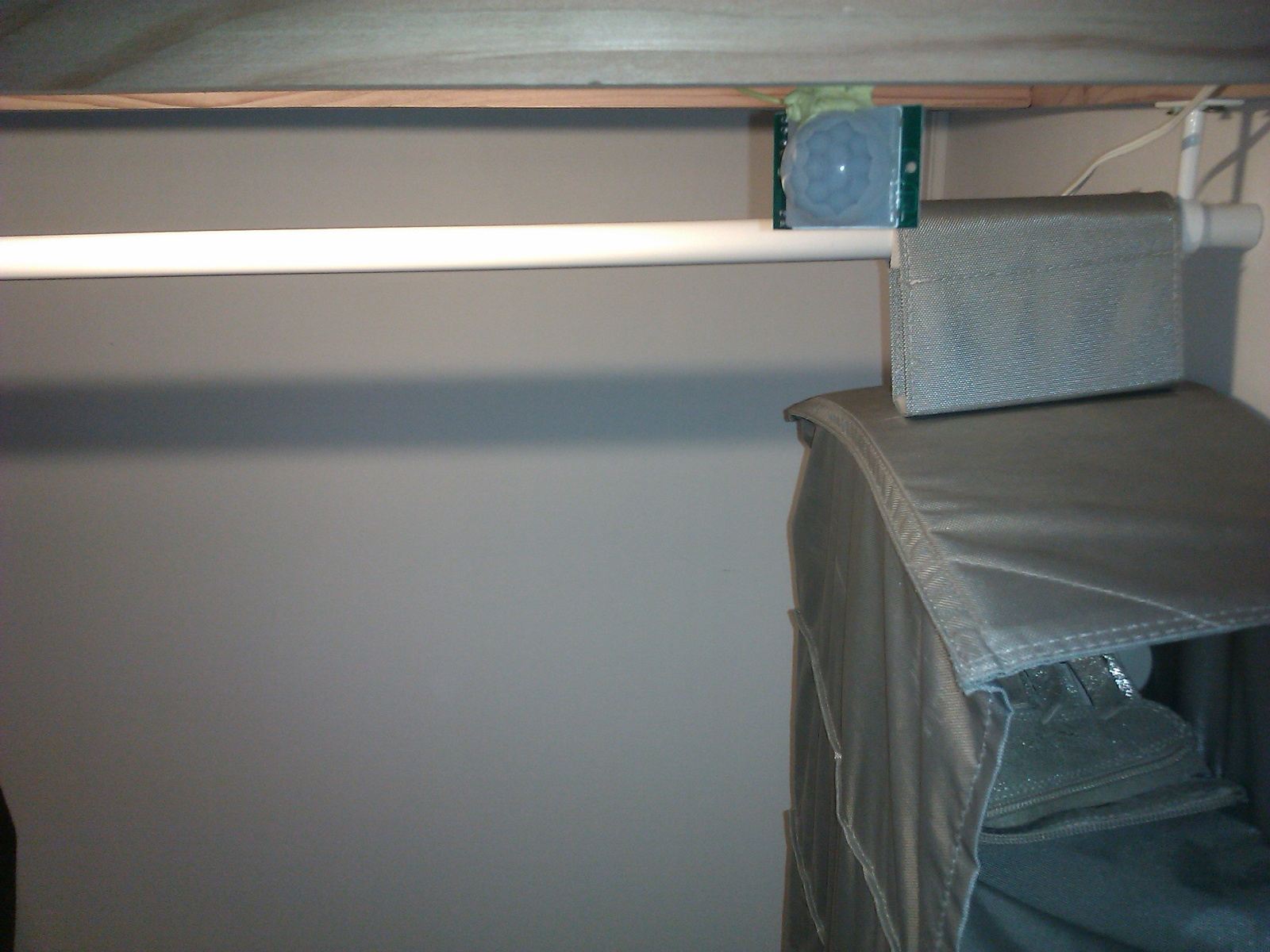
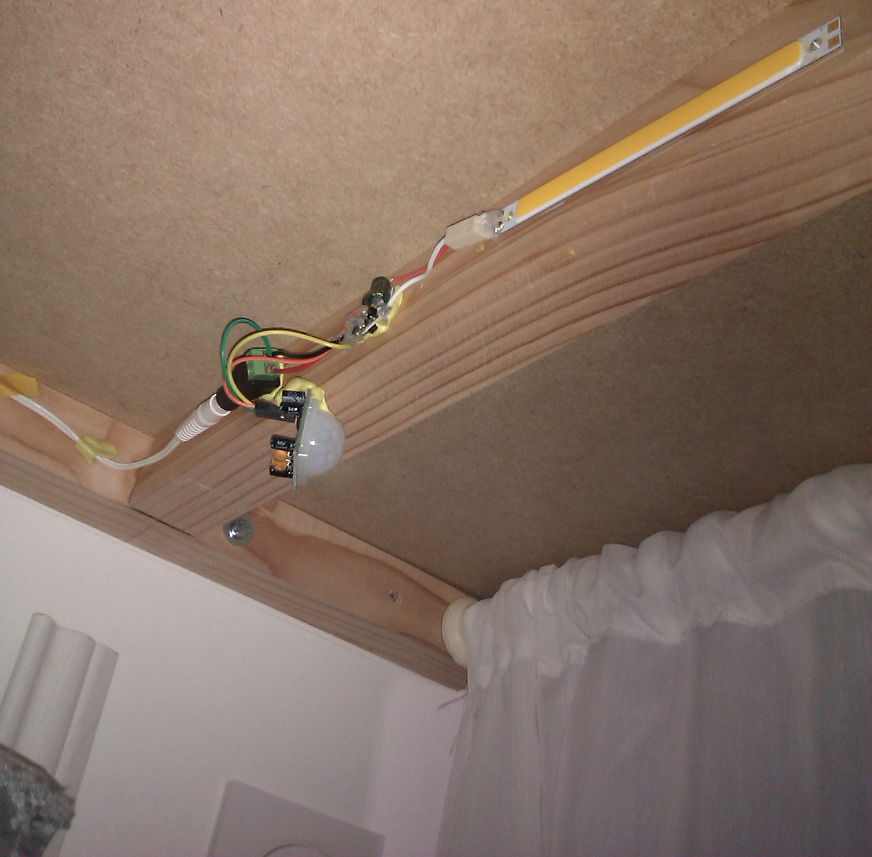
After installing the system, the PIR sensor is visible (although a curtain hides it):
The COB LED is hidden inside. It doesn’t shine into the eyes of the user directly, nor is it even visible unless you crouch and turn your head backwards:
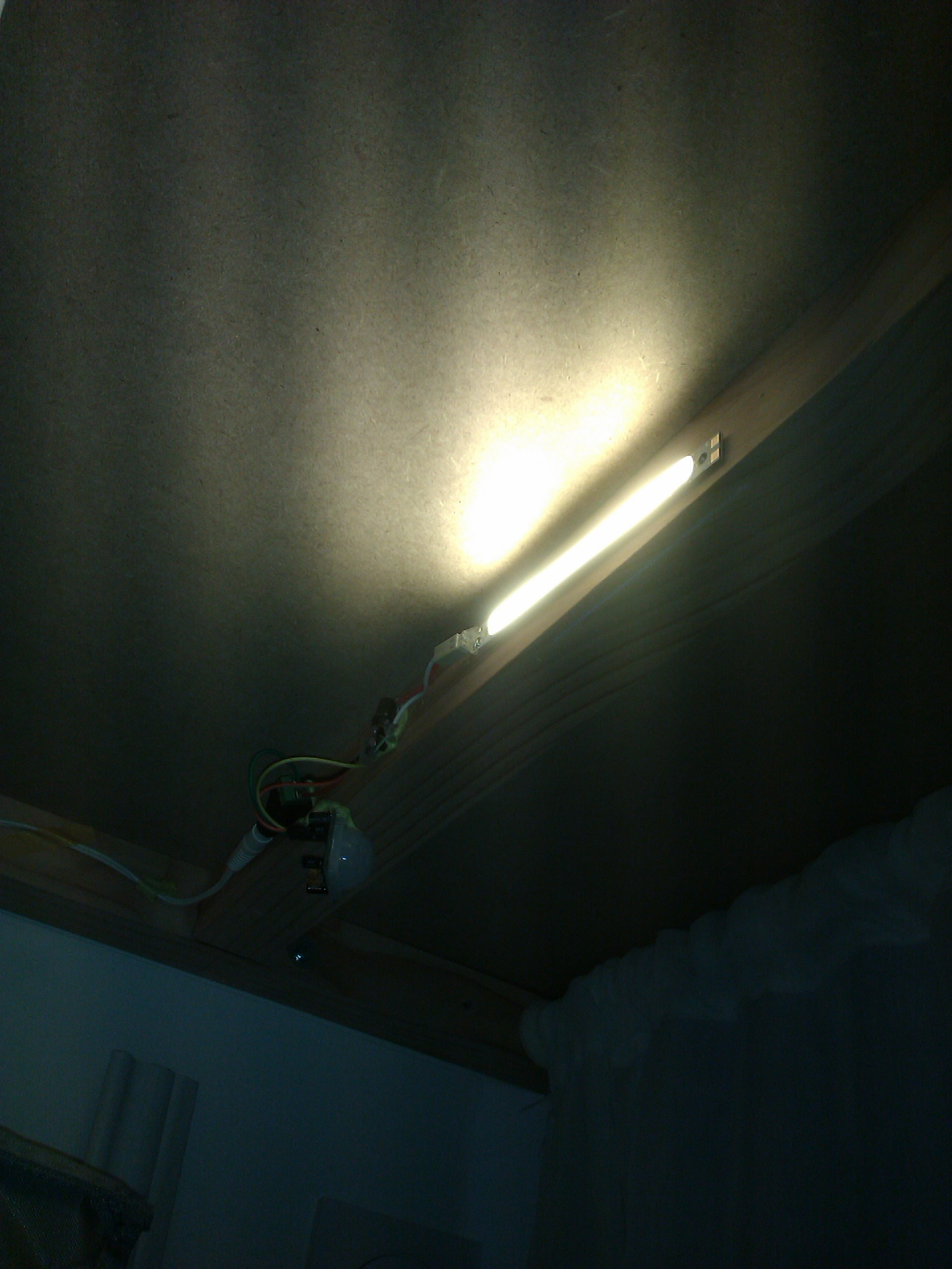
As of this writing it’s been used for two months and gives entire satisfaction. The one “flaw” is that the PIR sensor detects the user even through the curtain, so just passing in front of the closet will light it. It will the shut down after 30 seconds (the delay I set on the PIR sensor), so it’s not a big deal. The pictures don’t do the LED justice: it actually produces quite enough light.