Table of contents
- Introduction
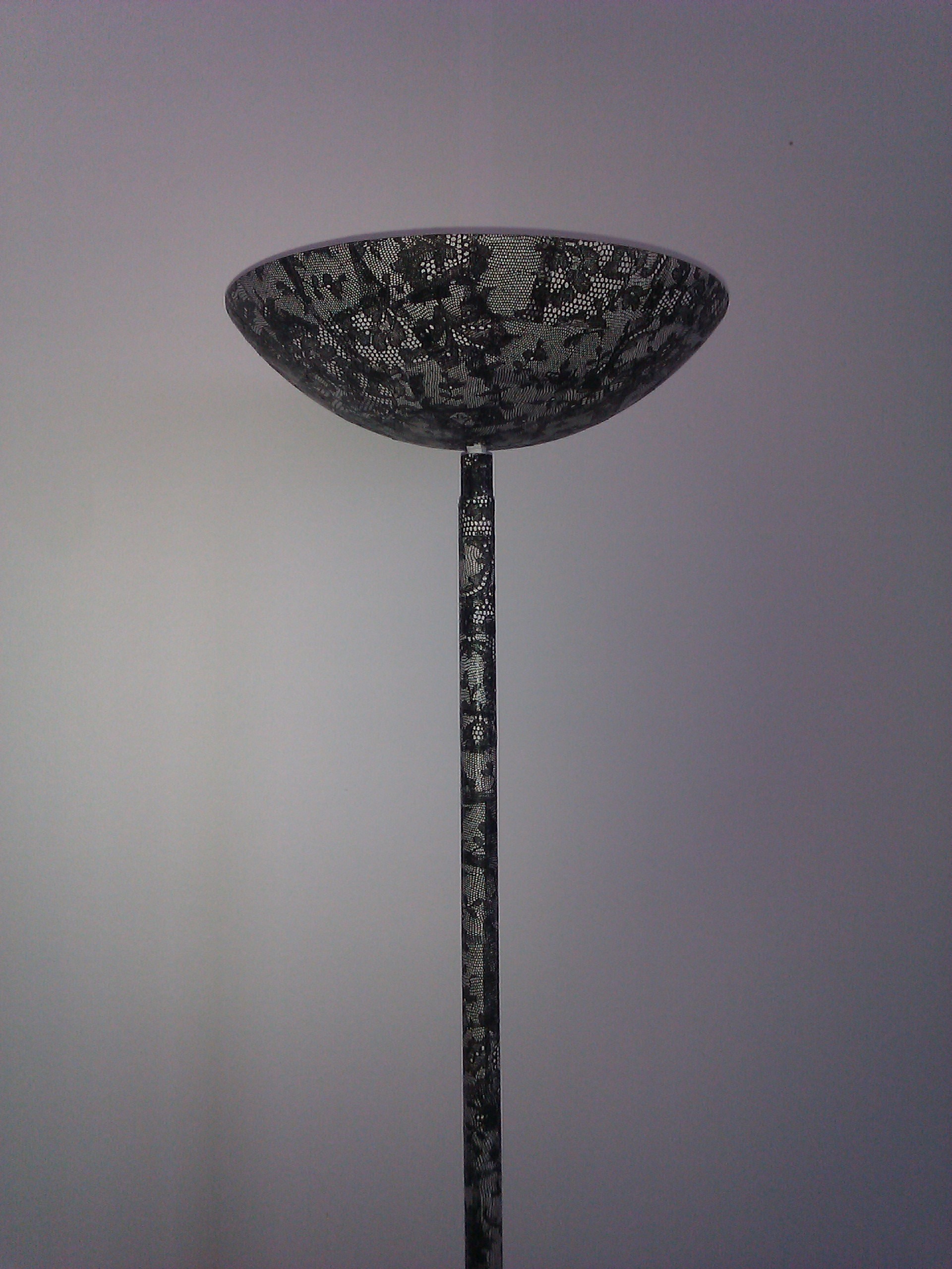
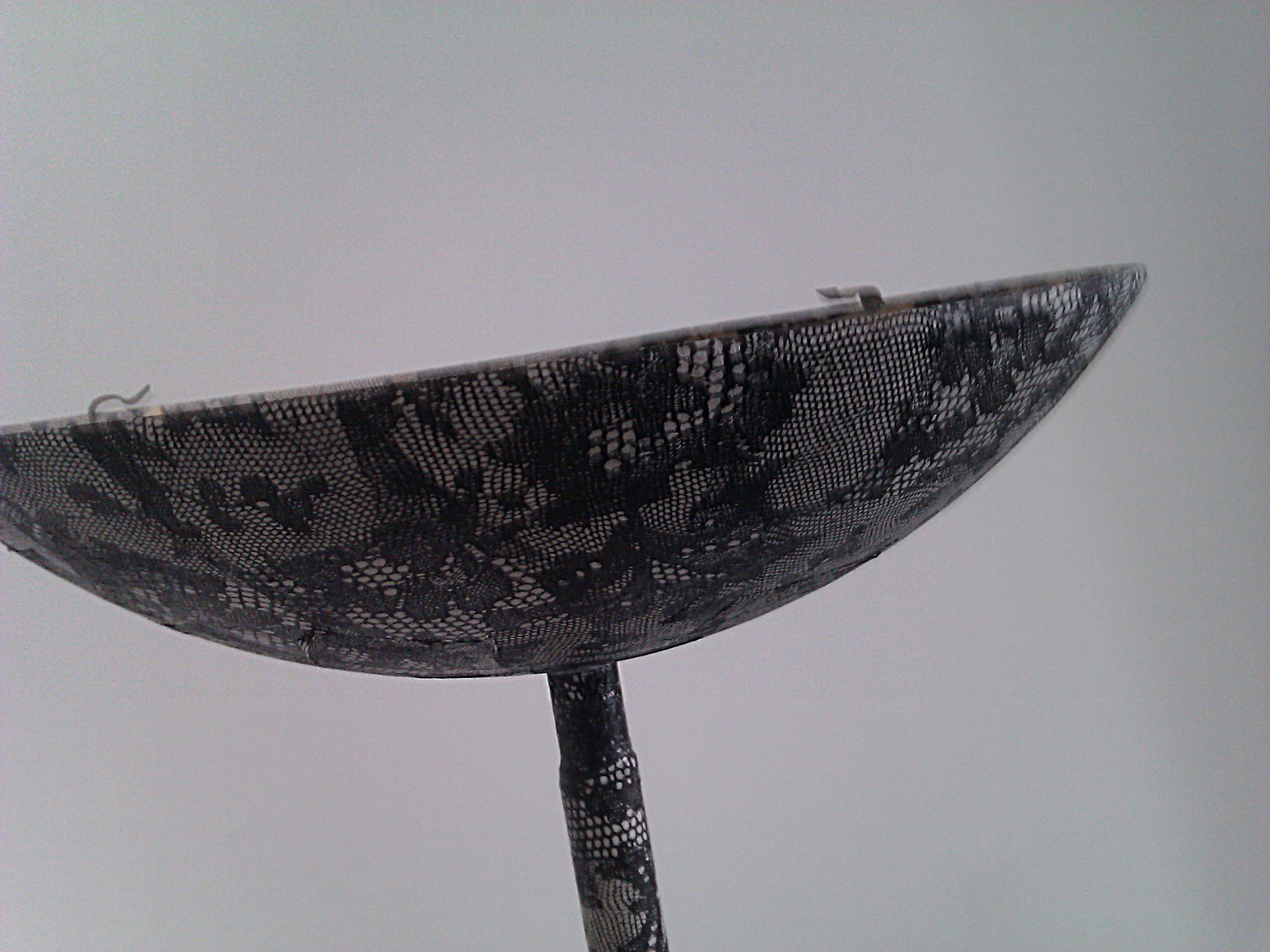
- What the lamp looks like
- Objectives
- LED technology
- Bill of materials
- Implementation - round 1
- Results - round 1
Introduction
I found a old halogen lamp in a dumpster years ago. My wife redecorated it, and I did minor fixes. Unfortunately, it doesn’t have a dimmer, nor a switch, and instead of spending time on improving a dying technology (I am not even sure R7S bulbs are still being sold in the EU), I decided to turn it into something modern! The 300W it consumed were too much anyway and I never really used it. With a LED-based solution I won’t have to think twice before powering it up!
What the lamp looks like
Objectives
- Light output > 700lm
- Warm white because cold white is bad for the eyes
- Auto-dimming based on ambient light level
- Presence detection
- Dimmable via remote control (from webapp/computer/smartphone)
The last three objectives will be done separately - and described in another article. They’re still relevant for this project because the result has to be compatible with what will be done later on, so we will take them into account when choosing parts.
LED technology
Typical LEDs, as used to report information in millions of electronics devices, draw about 20mA and generate a negligible amount of light. Those are hard to use for lighting unless you use a lot of them. This is what LED strips do - they use normal SMD LEDs, put a lot of them next to each other, and voila! Unfortunately a LED strip is physically bulky, and although you can cut it, you still need a significant length if you want to use it for lighting. Enter power LEDs. A power LED is a regular LED that is designed to emit a lot of light, at the cost of a high power consumption - and heat generation.
Driving a power LED
LEDs are current-driven devices: their voltage is almost a constant, and brightness is controlled by the current through them. If fed with a typical constant-voltage power supply, and for some reason the voltage increases even a little bit, this will translate into a big spike of current, which will make the LED very bright for a few seconds, then very hot, and then very dead. That is the issue of power LEDs: they need a driver, which is a constant-current power supply. That supply can be powered by the mains, or by constant-voltage power supply. A basic LED driver is a buck converter made of a transistor, an inductor, and a diode, although more elaborate designs exist. If we look at our objectives, we will likely require some electronics, probably in the form of a JeeNode microcontroller board (handling remote control, taking action on presence detection, automatically dimming, as well as, perhaps, temperature and current monitoring). Electronics usually need a constant-voltage supply, so we’ll go the way of a constant-voltage supply, and a separate LED driver.
Cooling a power LED
Power LEDs may have better efficiency than incandescent light bulbs, they still dissipate a lot of power as heat. However, unlike light bulbs, a power LED: - has a small surface, so convection is practically non-existent - does not radiate infrared, so radiation is practically non-existent - cannot stand higher temperatures than about 100°C (unlike light bulbs which are happier the hotter they get)
So heat has to be conducted away from the LED, using a heatsink. I have no idea of its volume, having never used power LEDs before, but based on my experience with computer chips even a 20W power LED will require a fairly big heatsink.
Choosing a power LED
There appears to be two types of power LEDs:
- 1-3W “stars” like  (taken from http://www.futurlec.com/)
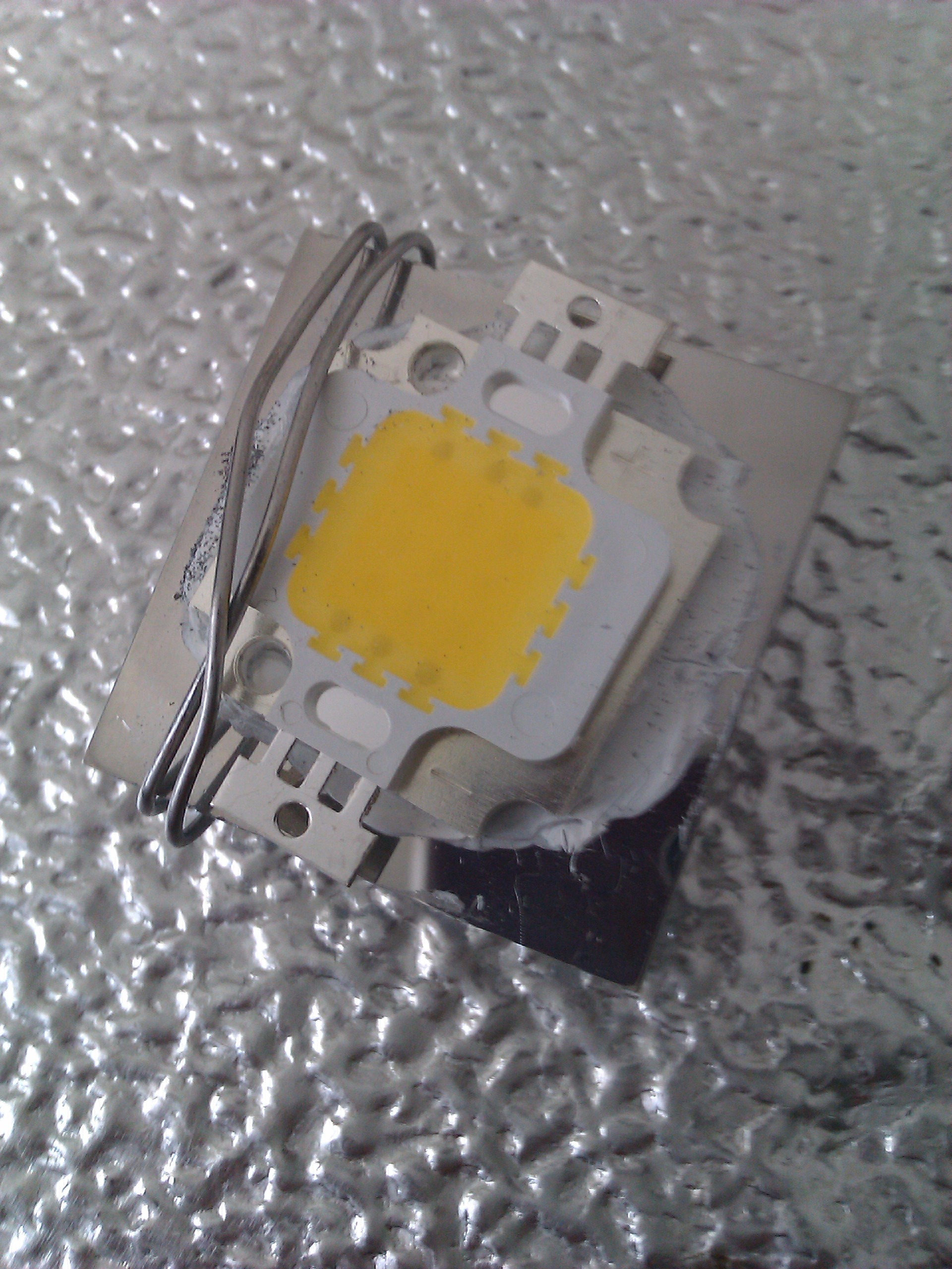
- 10W-50W Chip On Board (COB) LEDs, combining multiple LEDs into a single package (see http://www.cob-led.com/What-is-cob-LED-chips-on-board.html)
(taken from http://www.futurlec.com/)
- 10W-50W Chip On Board (COB) LEDs, combining multiple LEDs into a single package (see http://www.cob-led.com/What-is-cob-LED-chips-on-board.html)
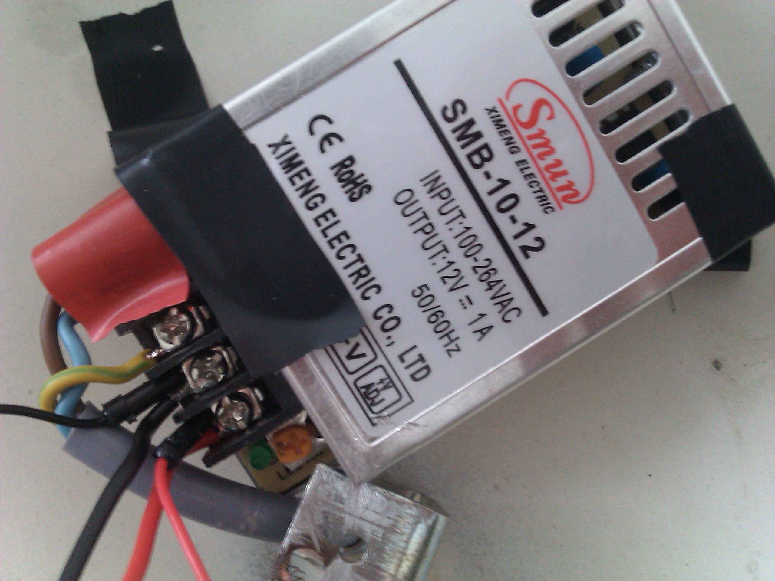
The stars appear to more or less have their own heatsinking, while COBs need a separate and somewhat bulky heatsink. COBs also typically require a fairly high forward voltage - 30V appears to be a common value. Higher voltages tend to translate to higher efficiencies in the power supplies. As I’m aiming for at least 700lm, I went for a power LED that can achieve this value, without making the wiring more complex - so a COB is probably a better choice. It’s better if forward voltage doesn’t exceed 12V: the electronics our project will have can’t really stand more than 12V, and most LED drivers appear to be buck converters (they reduce voltage, they can’t increase it). I picked a 10W COB from DealExtreme: https://www.dx.com/p/diy-10w-1000lm-3300k-warm-white-light-led-module-12v-164358 - this one is advertised to have a 12V forward voltage. 10W is not much, and to achieve higher light output it would be better to aim for 20W or even 30W. However, this would mean a bigger heatsink, and also a bigger power supply and driver. The problem is that the power supply will need to fit next to the LED in the top “bowl” of the lamp, and there is some room but not so much. Due to being curved, most of the volume up there is unusable. Looking at available metal-cased 12V 10W 20W and 30W power supplies, it turns out only the 10W ones will fit easily in the top part of the lamp. Non-China-designs don’t achieve a significant reduction in volume, so paying three times as much at Conrad or whatever popular reseller isn’t going to help. I picked a low-price, but CE-compliant, power supply, about which I reported in another article.
Bill of materials
We need:
- constant voltage 12V 1A power supply - 4EUR
- constant current DC-DC LED driver - 2EUR
- power LED - 5EUR
- heatsink - 2EUR
- microcontroller with PWM capability - 14EUR
Things could be simpler if there weren’t the “extra” objectives described at the beginning: An AC-DC constant current LED driver, a power LED and its heatsink, and we would be done.
I tried to find a 12V COB power LED - most COBs appear to be require around 30V, but 30V is too much for a microcontroller, and settled on the one listed above. I bought a generic heatsink to go with it, keeping in mind that there are serious physical constraints in this project. The microcontroller, as usual, will be a JeeNode. The LED driver was a bit more difficult to find, because DC-DC 10W 900mA LED drivers don’t appear to be that easy to find! I picked http://www.dx.com/p/mr16-1-3w-650-700ma-constant-current-regulated-led-driver-8-40v-input-13557. The description doesn’t appear to match, but the module is based on a PT4115 chip which is rated for 1.2A and has a DIM pin available. I will need to modify the module to change its current output to the 950mA my LED wants, and expose the DIM pin.
I also bought 7 meters of 3 * 0.75mm^2 electrical cable, to change that of the original lamp that was too short, and a male rewirable EU power plug with ground pin (which is the first time in my whole life that I bought an item more expensive on the Internet than in a physical shop).
Implementation - round 1
I’m calling “round 1” the prototype where things aren’t finalized. Pictures speak a thousand words, so I’ll just show a bunch of pictures and explain the few things that aren’t obvious from the picture.
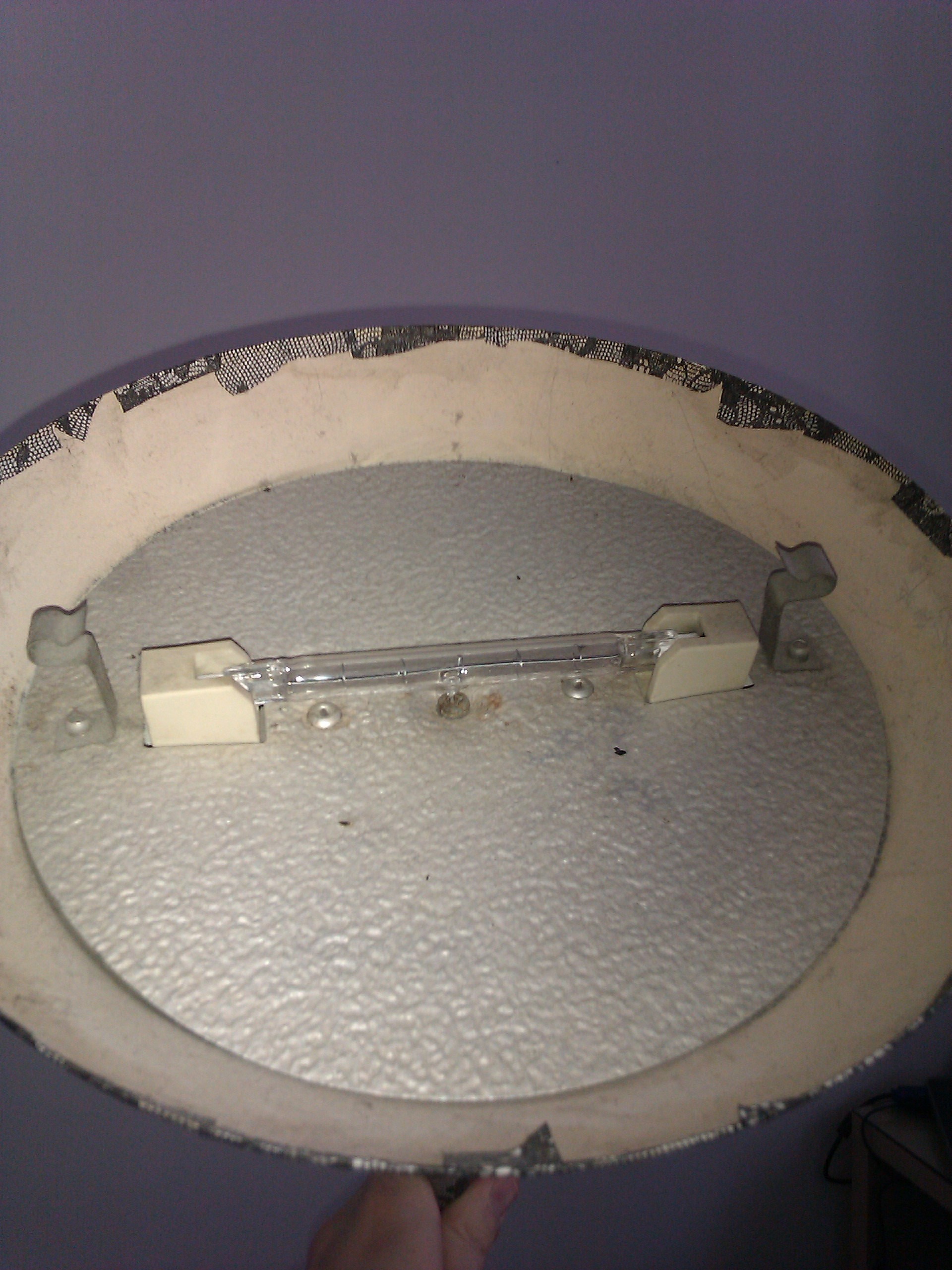
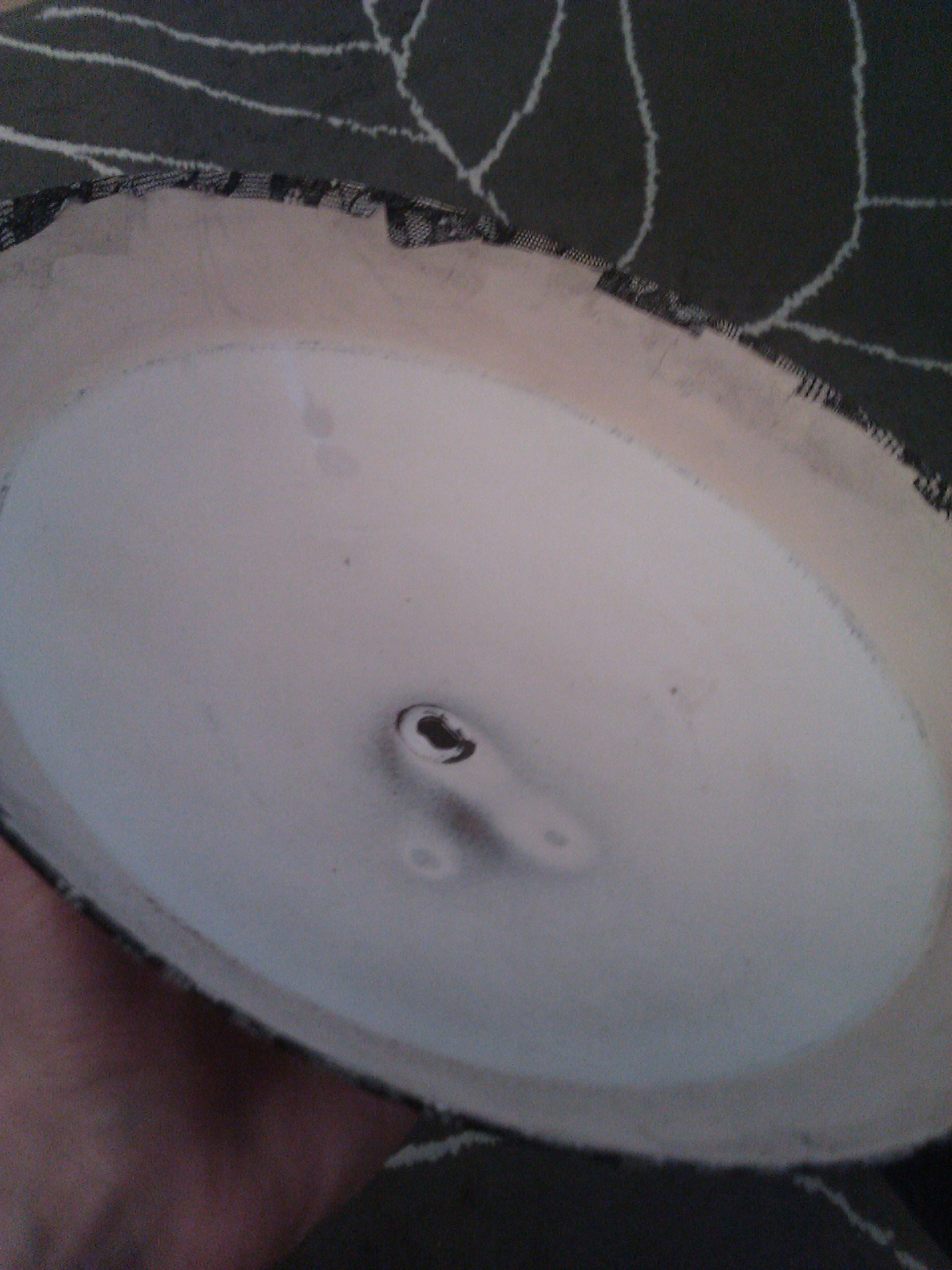
Ripping out the contents of the halogen lamp
Blind me test
Connect the power supply to the driver, the LED to the driver, don’t even bother with a heatsink, and start up everything. Congratulations, you’re blind for 15 minutes! Cut the power quickly as the LED will die without a heatsink. Seriously, don’t do that with power LEDs. Don’t ever watch them directly. If you don’t watch the LED directly, though, this is a first test to make sure that everything is running.
Modding the driver
The LED driver I bought is based on the exciting PT4115 chip. The chip itself isn’t enough, it needs to be added an inductor and a diode to make a complete LED driver, and it turns out that it’s easier and cheaper to buy a driver like I did and remove the unwanted components, than buy a PT4115 by itself and try to source the inductor.
What are the problems with the driver as I bought it?
- It’s made for AC input, so it has a bridge rectifier and an input capacitor, they will reduce efficiency and introduce an unacceptable voltage drop.
- It has MR16 pins for input, but I really just want to solder wires for input
- It is set up for 700mA with a 150 milliohm resistor, we want 900mA
- It doesn’t have a DIM wire, even though the PT4115 has a DIM input!
- The + and - at the output of the bridge are swapped :(
The mod was fairly easy to do:
- Unsolder (or rip out…) the four input diodes
- I haven’t touched the capacitor, but it can be removed too
- Solder red and black input wires at what used to be the output of the bridge, be sure you get the polarity right (the silkscreen is wrong on the unit I received, so you need to double check with the PT4115 datasheet where the GND and VDD pins are connected)
- Solder a tiny wire on the DIM pin of the PT4115 (make sure you add some tin on the pin, have tin on the wire, and it will be easy)
- Change the current sense SMD resistor marked R150 for the value you need, refer to the PT4115 datasheet for that.
Connecting everything
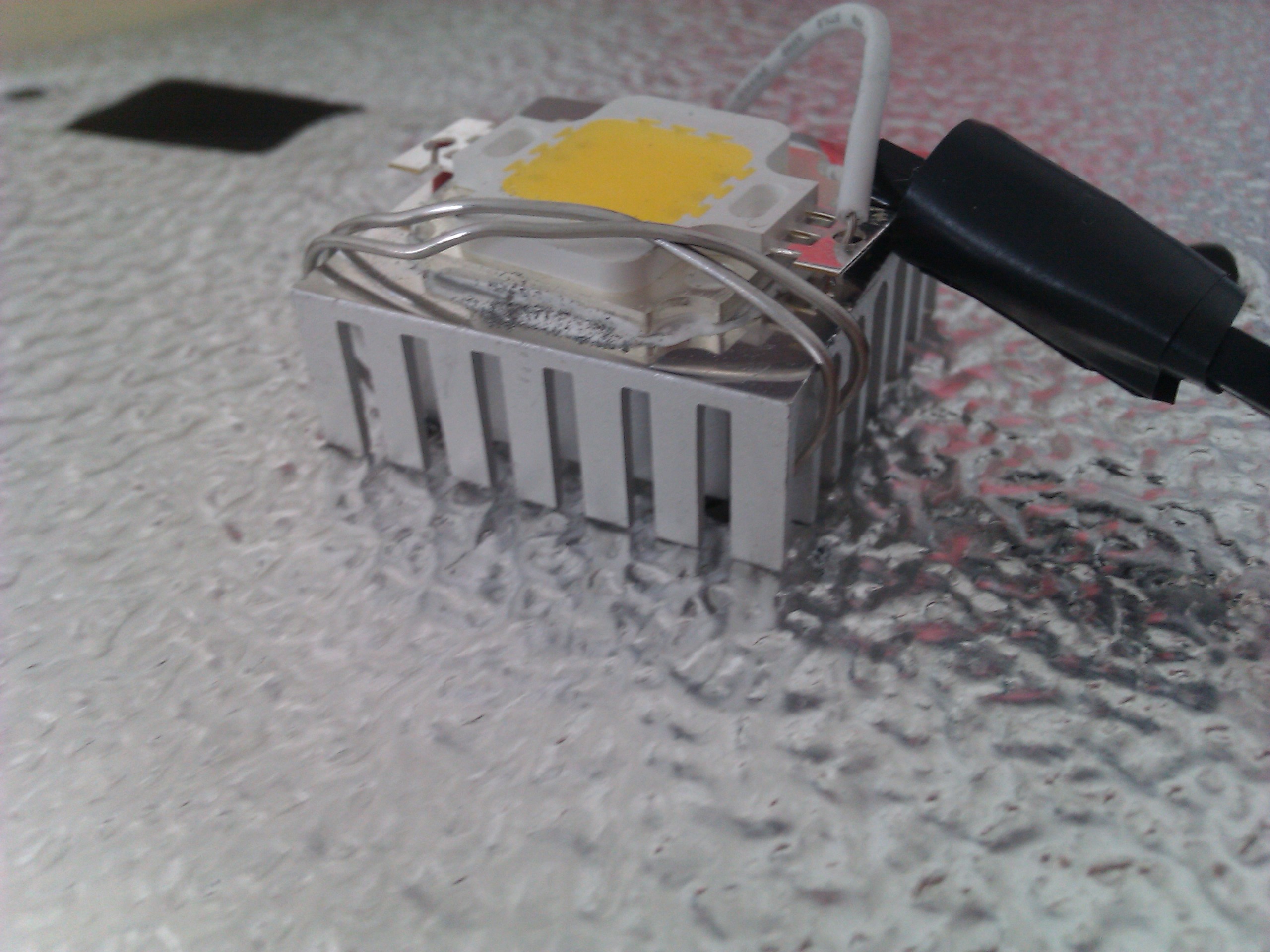
Metal case and mains means you need to have an earth connector. I’m somewhat unhappy with the connections of that power supply because they feel a little dangerous to me, I would like to have better isolation of the mains contacts, because a finger will easily touch them. I’ve polished the heatsink I bought, used some thermal paste to place the LED onto it. I didn’t even screw on the LED, the paste itself is enough for it to remain in place, even though contact would probably be better with some pressure.
It actually was easy enough to connect the microcontroller and its sensors, so I did it all at once. The main motivation behind this was to get temperature data to make sure my heatsinking was sufficient.
Pictures below.
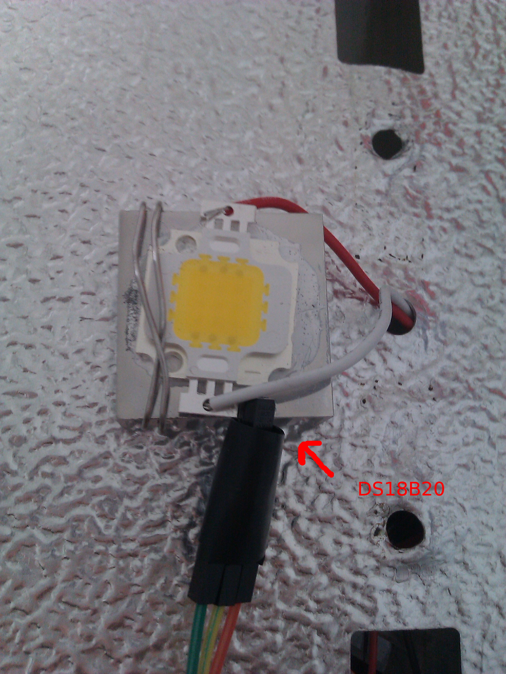

On the “Inside” picture I’ve labelled a few elements:
- A is the output of the LED driver, those wires go through the hole in the metal plate to connect to the LED
- B is the LED driver itself, the mod isn’t visible because it’s all wrapped in tape to avoid accidental contact with metal parts
- C is the DIM wire added the driver, it connects to one of the pins of the Jeenode
- D is the nRF24L01+ wireless transmitter attached to the Jeenode
- E are the wires that connect the DS18B20 temperature sensor to the Jeenode (will be replaced by a thermistor in the future)
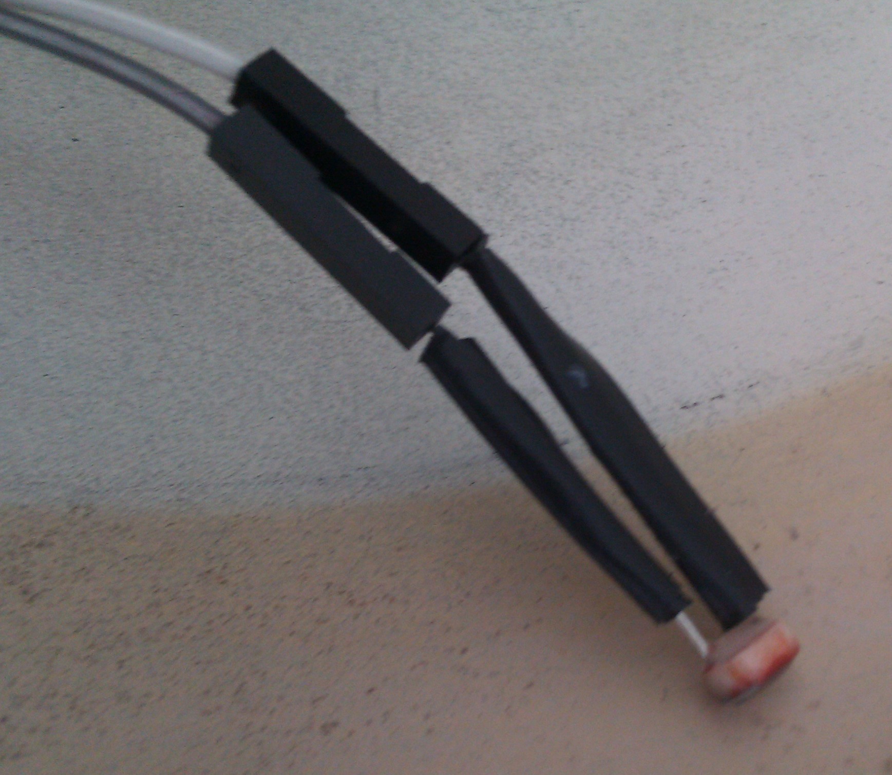
- F are the wires that connect the light dependant resistor to the Jeenode
- G are wires temporarily in place to connect the Jeenode to my computer to easily retrieve temperature data
Results - round 1
Light output
The current is at 700mA (so about 7 watts) instead of the rated 10 watts, because I don’t have an SMD resistor to replace the current sense resistor on the driver yet. And at 7 watts, the light output isn’t sufficient. It appears to generate somewhat less light than the 53W halogen bulb I have at the ceiling. I’ll mod the driver to get the rated power out of the LED, but I’m not holding my breath - 10W is just not enough. The 700lm objective is not enough.
Heatsink
The heatsink is probably too small, but I’ve measured a maximum temperature of 52°C with the probe in contact with it. I’ll estimate that means that the LED is running at about 95°C. Driving it at 900mA is probably going to exceed the safe operating temperature, so I’ll need a bigger heatsink. I have a CPU heatsink lying around, if I can physically fit it will help.
Oh my god this is ugly…
… I need to clean up the assembly. :)
To be continued…
See part 2.