In this article I will cover the improvements I made to my LED lamp. The prototype was a 10W COB LED, with its driver, and an Arduino-compatible microcontroller whose use wasn’t described.
Table of contents
Temperature control
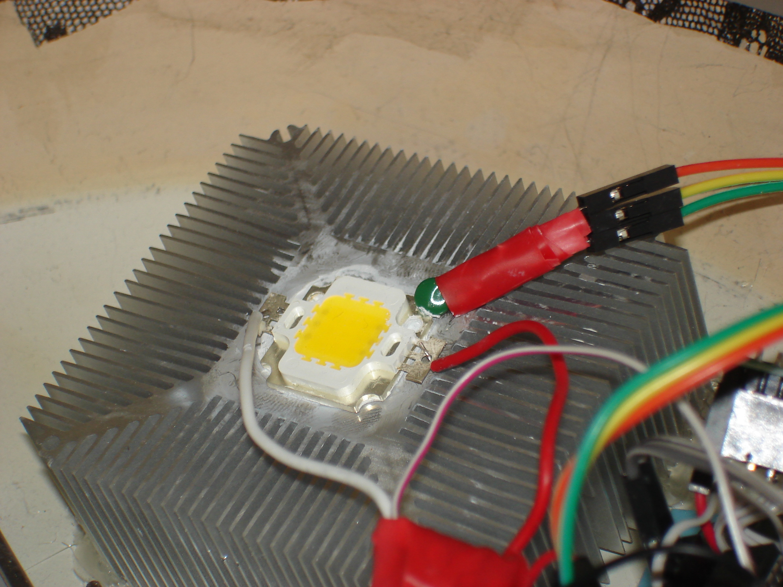
In practice, the heatsink temperature doesn’t exceed 55°C, but I didn’t know that before I measured it. As a safety measure for the LED, temperature control with auto shutdown was required. I originally used a DS18B20 I had lying around. It’s easy to interface with an Arduino, but it’s slow, somewhat expensive, and overkill. I bought a few thermistors instead, and replaced the DS18B20 with one of them. This was more involved than I had originally expected, because translating the value on the ADC to a temperature is far from trivial. Technically, retrieving the temperature from the thermistor isn’t needed. I could have been content with setting a threshold based on the ADC value (instead of the temperature), which I could have determined by putting the thermistor in water at a more-or-less known temperature of say 55°C. If you are going to do a thermistor-based temperature threshold system, I advise you go this way. It will take some time for you to get a known water temperature, and this will not be very precise, but it’s going to be much shorter than writing the code to find the temperature from the ADC value - and I’m willing to bet that the precision won’t be much lower.
To get the temperature, you have to first retrieve the current resistance of the thermistor based on the ADC value. The relationship is non-linear and not completely obvious. Then, you can apply a theoretical model (whose parameters are given to you in the thermistor’s datasheet) to get the temperature based on the resistance value. Precision is abysmal, and forget about using the internal pull-up resistor of the AVR because its value is defined at +/-50%. My first attempt (with correct theoretical computations) gave me an ambient temperature in my office of 28°C (it was 21°C). So do yourself a favor and if you don’t really need the temperature, but just an approximate answer to “is this value exceeded?”, use the technique described in the paragraph above.
If you really enjoy pain, you’re welcome to double check my computations below. (Because blindly reusing code you don’t understand is not something either you or I ever do, right?)
  	int get_temperature()
	{
		// We have Uth = Rth * E / (R1 + Rth)
		// let V = Uth * 1023 / E, value read by the ADC
		// <=> V = 1023 * Rth / (R1 + Rth)
		// solve in Rth :
		// Rth = R1 * V / (1023 - V)

		// Once we have Rth, use beta parameter equation for NTC:
		// T = Beta / ln (Rth / R0 * exp(-Beta/T0))

		unsigned int adc = analogRead(THERM_PIN);
		const unsigned long int R1 = 21900;
		const float Beta = 4400.0;
		const float Beta_R0 = 100000.0;
		const float Beta_T0 = 25.0+273.0;
		float Rth = R1 * adc / (float)(1023 - adc);

		float T = Beta / log(Rth / (Beta_R0 * exp(-Beta / Beta_T0))) - 273.0;

		return (int)(T * 100.0);
	}
My code checks temperature every 30 seconds, and reduces the light output (= the dimming factor on the LED driver) if the LED gets too hot. It also sends an alarm over the radio so I can know about it:
  	if (millis() > next_temperature_check_at) {
		int temp = get_temperature();
		next_temperature_check_at = millis() + 30000;
		if (temp > 8000) {
			printf("Thermal emergency, temp %d.", temp);
			radio_send_temperature('E', temp);
			thermal_override = 1;
			decrease_light_output(1.0);
		} else if (temp > 6000) {// 60 C
			printf("Thermal alarm, temp %d.", temp);
			radio_send_temperature('A', temp);
			thermal_override = 1;
			decrease_light_output(0.1);
			next_temperature_check_at = millis() + 5000;
		} else if (thermal_override && temp < 5500) {
			radio_send_temperature('0', temp);
			printf("End thermal alarm.");
			thermal_override = 0;
		}
	}
Auto-dimming
A light-dependent resistor is connected to another ADC, and I use it to sense to ambient light level. This way, the lamp automatically starts (and gradually increases power) when the sun sets or if a sudden cloud cover appears, and it stops when the light level is high enough. This works beautifully except for two important issues:
- it has to be installed so that it senses the room light level, and not the light beam from the LED
- the lamp is not powerful enough to have a significant effect, so in practice it’s all-or-nothing and rarely at e.g. 50% brightness
The second point is simply a matter of power, and in future realizations I’ll go for a 20W or 30W LED and the problem will disappear. The first point is all the more important that I want the lamp to look good, and currently the light sensor makes this impossible (see picture).

Remote control
I used one of the nRF24L01+ modules I love so much, to receive commands and send messages. The LED lamp understands the following commands:
- SET TARGET LIGHT LEVEL - takes a percentage representing the target ambient light level to maintain in the room. 0 means shut everything down. The lamp will reply, giving its current target light level, expressed in ADC value:
Ledlamp remote reply: lamp is on, light level target 120
- QUERY - returns temperature and other status about the lamp:
      	Ledlamp thermal notify: temp is 2736
	Ledlamp remote reply: lamp is off
	Ledlamp current light level notify: 119
	Ledlamp current duty cycle notify: 0
As explained above it can also asynchronously transmit thermal alarms when they happen, so that I know why the light goes off all of a sudden. This never happened so far but might with greater power levels in the future; and asynchronously transmit when it raises or lowers the duty cycle (in response to a variation of the room light level), as follows:
      	Ledlamp increased power, duty cycle 67
	Ledlamp increased power, duty cycle 68
	Ledlamp increased power, duty cycle 69
	Ledlamp increased power, duty cycle 70
	Ledlamp increased power, duty cycle 71
	Ledlamp increased power, duty cycle 72
My Raspberry Pi, with this program, handles communications with the LED lamp (as well as my gas counter and sunrise alarm clock which I’ll write about later).
The command stream is exposed as a TCP socket with netcat, allowing any of my computers to send commands to the LED lamp. My main computer has the following in /etc/pm/sleep.d:
          #!/bin/sh

	killall nc
	case "$1" in
			hibernate|suspend)
					echo LEDLAMP 0 | nc -w 1 alarmpi 45888
					;;
			thaw|resume)
					echo LEDLAMP 30 | nc -w 1 alarmpi 45888
					;;
			*) exit 0
					;;
	esac
When the computer goes to sleep (automatically after 30 minutes of inactivity thanks to xautolock), the lamp shuts down - with a ten second delay allowing me to exit the room and still see where I’m going. When the computer wakes up, the lamp gets the order to maintain 30% of its maximal ambient light level. The 30 figure doesn’t have much meaning, it corresponds to a fairly low level that I find appropriate for the start of my day. I raise it to “as bright as you can” during the work day.
Higher power
Recall that the driver I used was set up for 750mA output. I changed the current sense resistor to a 0.12ohm 0805 SMD resistor, to increase the output to about 800mA (more would be expected but would need a higher voltage, and the regulator on the JeeNode is rated for 13V max - my next LED-based project will not use a JeeNode for that reason). The resistor was pretty hard to find in reasonable quantities and at a reasonable price. (Those components are typically sold in reels of 5000, and you can buy strips of said reel from any well known reseller such as RadioMarkup, err, I mean, RadioSpares. The price for 5 of those resistors is literally twice the price of the full, assembled driver.)
I used a much bigger, CPU heatsink. This was both to clean up the assembly (see further below) and ensure correct heat dissipation, as I had determined the previous heatsink to be a bit “light”. An actual CPU heatsink helps a lot, and I think it really shows how big heatsinks have to be for LED devices. A 20W or 30W LED would probably need an even bigger one, which would be both hard to find and hard to fit!
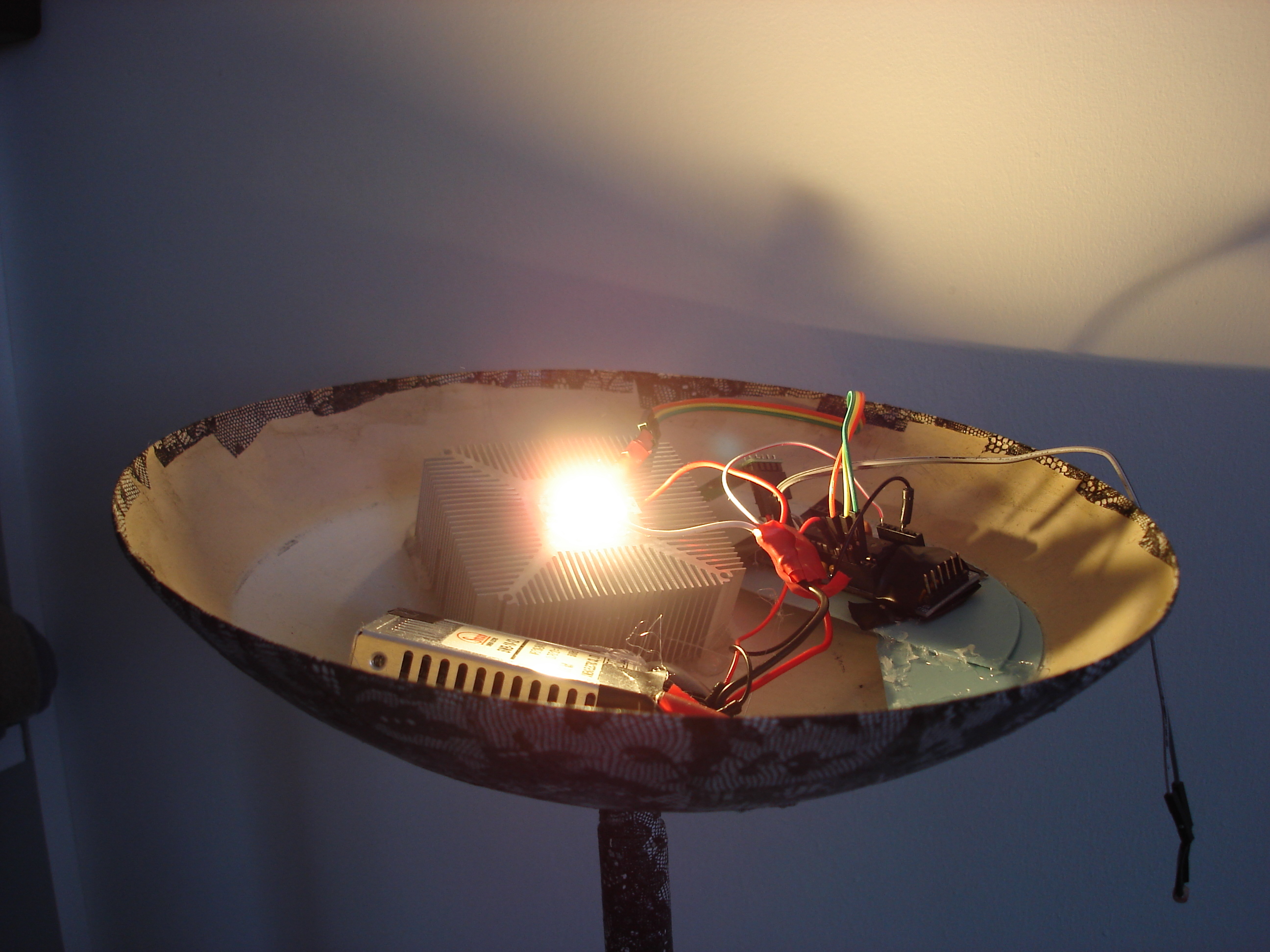
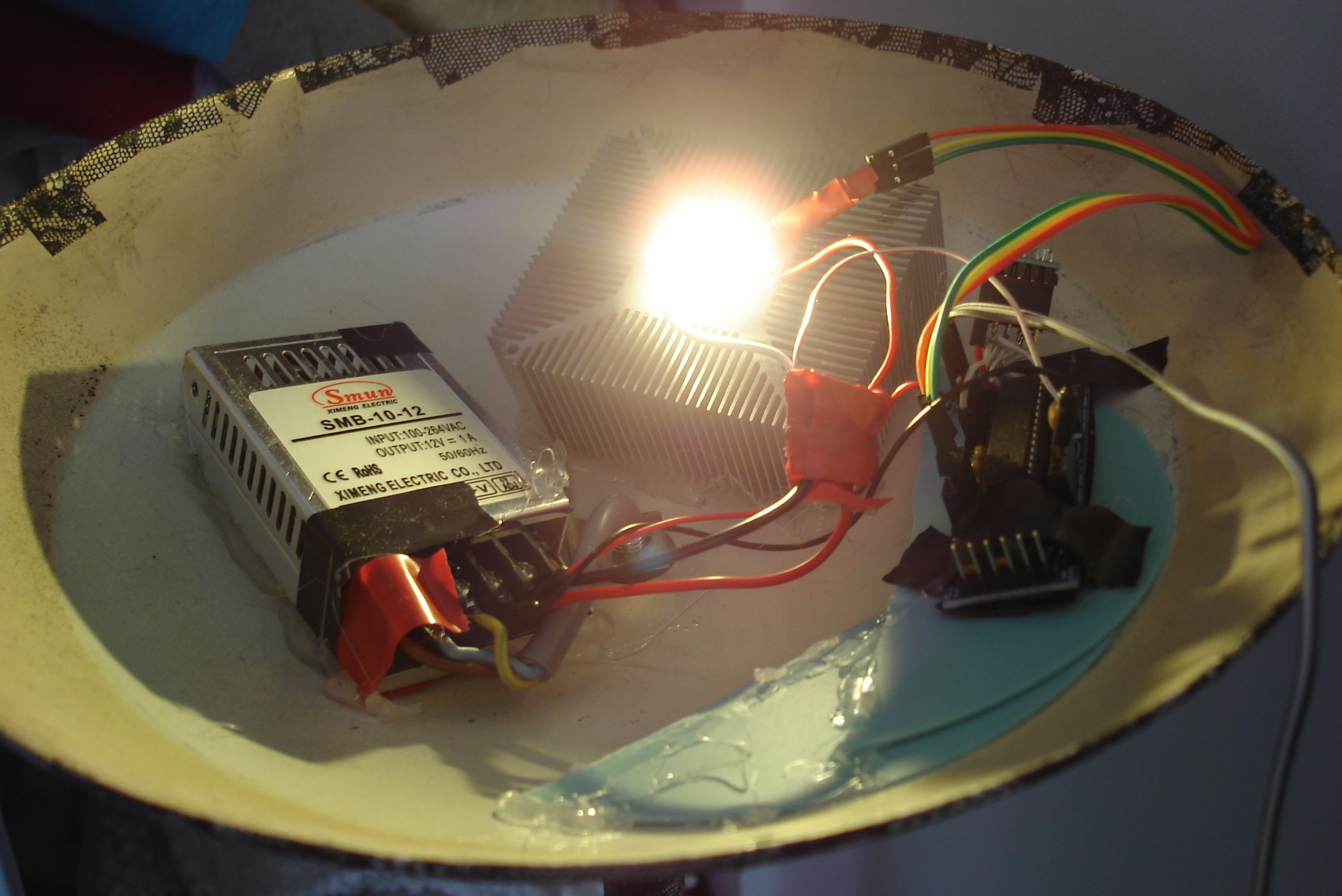
Cleaner assembly
It was my experience so far that hot glue didn’t stick really well to metal. Well, I had the exact opposite experience with this lamp - I really was out of ideas about how to set everything in place, given that the “bowl” was curved, so I was desperate and tried the hot glue gun. It holds everything in place perfectly!
I still haven’t used connectors, so most of my connections are individual wires, sometimes not even soldered, but at least the inside of the lamp looks fairly clean, is not dangerous, and is significantly less brittle than before.
What is still missing
Current level monitoring would be good. You do that with a shunt resistor and I don’t have any lying around, so I haven’t done it. Higher power would be good, but it would require that I change everything (the power supply is maxed out @12V 1A, the JeeNode can’t take higher than 13V, the LED is rated for ~950mA @12V, and the cooling solution is probably a bit limited).
Presence detection still hasn’t been implemented. I know how to do it technically (a PIR module such as this one will work, as evidenced by my bathroom lighting), but it would have the same problem as the light sensor: it would be ugly. Presence detection is made mostly useless by the /etc/pm/sleep.d hook on my computer: my being in the room and my computer being on are very strongly correlated, so practically the lamp is on when I’m in the room and off when I leave it.
I’m still quite excited to have gotten this to work so easily, even though it’s not perfect, for a first power LED project it’s a success.
Let me know if you have questions!