In this article I will describe the baby monitor I built, reusing the case of an old crappy one, and re-doing all of the electronics from scratch. I tore down the crappy one in a previous article (in French).
Objectives
The objective is, of course, to be able to listen to the sounds of the baby remotely. There are two devices: the transmitter and the receiver. The transmitter must:
- capture sound in the room it is in
- decide if that sound is loud enough to wake up the receiver
- transmit sound data over wifi to the receiver
The receiver must:
- receive sound over wifi
- amplify it and play it on speaker
- have a button to force sound transmission
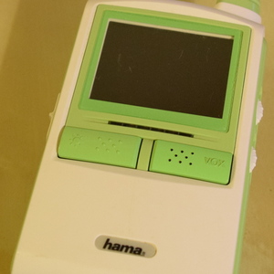
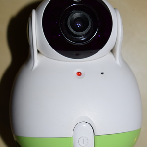
In addition, both devices must be cheap, and “wife-proof”, that is, look good enough for her not to even notice that it is not a commercial product, so she doesn’t get the slightest opportunity to complain about yet another duct-tape project (scroll down to the pictures to see the irony). This last point is usually hard to achive, but not this time: I happened to have an old, crappy babyphone lying around. I tore it down, removed all the electronics (actually de-soldering components but keeping the boards), and had the cases ready to use for my project. While this turned out to be great in terms of looks, it made the job much harder due to the space constraints inside of the case, in particular for the transmitter.
I based both devices on an ESP8266, so I would have fast, reliable, and cheap wifi access. The ESP8266 is not a perfect fit for a project like that : it doesn’t have a decent ADC, it doesn’t have a decent DAC, and it tends to be electrically noisy in such a way that the electret pickup circuit can be affected by wifi transfers. On the other hand it’s cheap, easy to use, and has plenty of processing power.
Hardware
Transmitter
A cheap electret will be amplified and fed into an external SPI ADC. The ESP8266 speaks to the ADC from an interrupt handler running at whatever sampling rate I choose (originally 12.5kHz, now 20kHz, possibly more later).
Microphone
I re-used the electret of the old baby monitor I had. I also bought a few from eBay of the same dimensions and couldn’t hear any difference.
An electret is a device that requires a stable bias voltage, and that outputs a signal with a magnitude in tens of millivolts. This is too small to directly connect to an ADC, so it has to be amplified. Although I did know a little about op-amps, I never made my own design using one, so I used this circuit to amplify the signal from the microphone. As it turned out, I had major noise issues. This op-amp is simply not great, which doesn’t help, but the main issue was that I was running long leads from the board to the electret (about 10 centimeters) The leads were, due to the space constraints inside and the fact that I had not oriented the board in the best possible way, running very close to the antenna of the ESP8266. This injected a lot of noise, such that you could hear what was going on in the room, but there was a very loud noise on top of it, actually louder than any sounds in the room.
I solved that problem by doing three things:
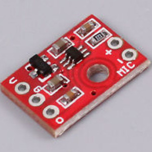
- amplifying as close to the electret as possible, using a ready made MAX9812 electret amplifier module
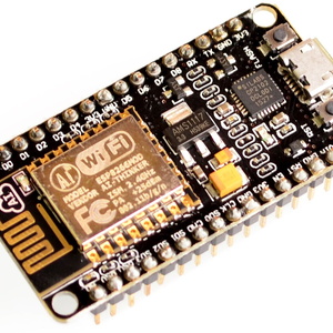
- moving from an ESP12F module with an MCP1702-33 voltage regulator to a NodeMCU Amica board that features its own power supply circuitry. This had the effect of reducing power supply noise a little bit.
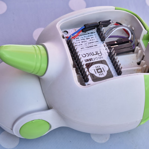
- scrapping the board I had painstakingly assembled (actually re-using it for a completely different project), and re-doing the layout from scratch to put the ESP8266 as far away as possible from the analog circuitry. (The ESP8266 Amica board ended up in what used to be the battery compartment of the device.)
This eliminated the noise, but not LM358: the MAX9812 only amplifies by a factor of 10x, and that isn’t enough. Ready-made electret amplifier modules that amplified more were significantly more expensive, so I elected to do my own amplification with the LM358 I already had, to bring the total amplification to about 150x.
ADC
The ADC needs to be audio capable (able to sample at 20kHz or more), cheap, and preferably using SPI (because the ESP8266 has a hardware SPI interface, but no hardware I2C interface). I picked the 12-bit MCP3201, and I am very happy with it. I went for the DIP package, if I had to do it again I would probably buy it in a surface mount package. It’s not usually much harder to solder and occupies less physical space - which in many projects, including this one, can be a real advantage. The MCP3201 is single channel. More channels didn’t cost all that much more, but required more pins, and I couldn’t afford that on the 5x5 cm board the project had to fit on.
Receiver
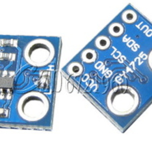
DAC
I didn’t manage to find an SPI DAC for cheap enough, so I bought an MCP4725 12-bit I2C DAC, pre-soldered on a small module (the package is so tiny that this was necessary). No particular problem there either, except that sending twenty thousand samples per second to the I2C DAC with an ESP8266 does consume a lot of CPU time, to the extent that the I2C communication is, as far as I can tell, the bottleneck in increasing the sampling rate.
Amplifier
I re-used the speaker of the original baby monitor, of course, but couldn’t readily re-use the amplifier chip because it was part of a relatively complex electronics board (that I needed to saw to reuse parts of). I picked a PAM8403 amplifier module. Its input resistor was set up for a very high gain, and for this application I needed a lower gain, so I had to modify the SMD resistor that the module shipped with, and of course wire the original monitor’s volume potentiometer.
Pictures
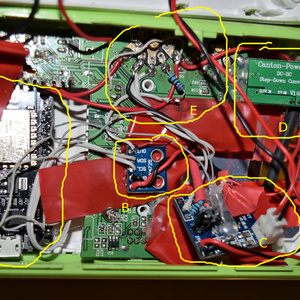
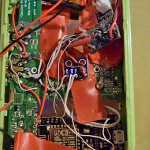
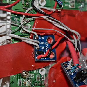
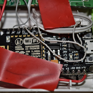
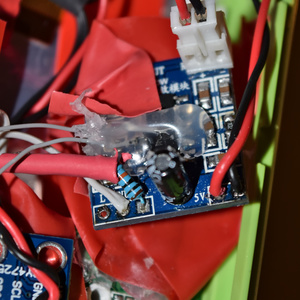
I apologize for not having pictures of the transmitter side - it’s the side that looks good and was done cleanly. The transmitter, as you can see, was hacked together in a pretty ugly way. It does work very well, but the insides look terrible. It was hard to fit everything properly due to the very small amount of free space, and the fact that I wanted to re-use the jack connector and potentiometers forced me to saw off parts of the original PCB, and fit my modules wherever I could. This build doesn’t use a PCB, rather, everything is connected by wires (hence the ugliness), and hot glue keeps things in place.
- A is the NodeMCU board
- B is the DAC module
- C is the amplifier module
- D is the boost module used to produce 3.3V from the power supply’s 6V (not used by the NodeMCU which has an AMS1117 onboard)
- E is the on/off and volume potentiometer. The resistor is here to increase its resistance so the amplifier doesn’t get a full scale signal, which it hates.
Detailed pictures follow, but unfortunately I got the aperture settings wrong, so they are ugly. Sorry about that.
Software
I used the Arduino framework for ESP8266, as it makes things slightly easier than writing directly on top of the Espressif SDK; although I ended up writing a lot of plumbing code for performance or correctness reasons. The full code is available there: https://github.com/sven337/jeenode/blob/master/babymonitor/xmit/xmit.ino https://github.com/sven337/jeenode/blob/master/babymonitor/recv/recv.ino
Sampling
The transmitter uses the hardware timer to set up an interrupt at the desired sampling rate. That interrupt reads a sample from the ADC, poking the SPI registers directly for greater speed. A double buffer of 700 samples is used to store the data.
Envelope detection
When the buffer is full, the main loop of the program will do some processing aimed at determining whether the recorded sound constitutes baby cries (that we want to transfer) or silence (that we don’t want to transfer). This is very important, as we don’t want the receiver to be always on: the level of background noise may not be much, but it’s always annoying. In fact, one of the very reasons for that project is that the old baby monitor we picked up for cheap left the receiver constantly on!
Silence value
The samples are unsigned 12 bit integers and are supposed to be centered on Vcc/2 (thanks to a bias voltage applied to the positive input of the LM358). So the theoretical value of silence is 2048, not 0… but it’s only theoretical. In reality my resistor divider doesn’t apply exactly Vcc/2, and I want the software silence level to adjust automatically to any changes to the circuitry. Therefore, the program calculates the silence value, to use in the envelope threshold calculation. The silence value is, very simply, the average of the signal over a long period of time! The easiest implementation of this is an exponential moving average.
Envelope detection
To make the decision of sending or not sending sound, I implemented an envelope threshold algorithm. The idea is to trigger on loud noises. To know if a noise is loud or not, one common, simple method is to compute the envelope of the signal. The envelope is what you get when you rectify and lowpass-filter the signal, in analog terms you can obtain it with two diodes and a capacitor. In fact, many “sound level detector” projects do this analog processing… but we don’t want to alter the analog signal, as we need the sound data, so we’re doing it digitally, which is easier anyway. By subtracting the silence value from the rectified signal, we get a value that indicates how loud the sound currently is. If that value exceeds a configurable threshold, the transmitter decides to send sound.
This works very well in practice. Of course the threshold has to be tweaked a little bit, based on how far from the baby the monitor is. That is why I am thinking about making it reconfigurable on-the-fly with a potentiometer on the receiver side.
Wifi transfer
Samples are 12 bit, but stored as 16 bit because this is what the ADC gives me, and packing them tightly isn’t actually efficient in terms of space savings (see below). So a buffer of 700 samples is 1400 bytes, which fit in a single UDP packet. As soon as the code has decided to transfer sound data over wifi, the whole 700 sample buffer will be sent as a single packet to the current target. That target can be the receiver, but also the computer, for debugging purposes (and later, when my son starts speaking, to actually record some of his crib talk). At the moment it only transfers data to a single target, but multicast is on the list of potential improvements. The target is, by default, the receiver, but it can be changed using the command channel (see below).
Compression
As the ADC outputs 16 bits (although only 12 bits are useful), I decided to transfer the 16 bits instead of packing the samples tightly. The reason for that is that packing the samples tightly actually requires some non completely trivial bit arithmetic, which isn’t going to improve the performance characteristics of the system, and it wasn’t necessary during development anyway. The system only consumes 40kB/s of bandwidth and my wifi is more than capable of doing that.
Still, for the sake of doing things well, I tried to compress the data sent over wifi. It is not possible to use MP3 or any similar “real” audio compression format, as that would require a hardware DSP. I actually bought one, a VS1053 DSP that has an ADC, a DAC, and can encode and decode OGG. The original intent was to use it as part of the project, but I ended up going the way that is described in this article, and I don’t regret it. Some dumb compression can still be done. Packing the samples tightly from 16 bits to 12 bits yields a constant gain of 25%, a good figure, but can we do better? It turns out that we actually can!
Instead of packing the samples tightly, we will attempt to make smart use of the extra bits in each sample. We’ll use the first one to indicate if the sample is “compressed”, and the 7 remaining ones in the byte will encode the delta of that sample from the previous one. I call that “delta7”.
This way, uncompressed samples remain on 16 bits (with 4 unused bits), and compressed samples take 8 bits, looking like this: 1SMMMMMM, where S is a sign bit, and M are the magnitude bits. This is a signed value, but not encoded in two’s complement, because it is surprisingly hard to implement 7 bit signed integers in C with two’s complement, while using the sign-and-magnitude encoding is much easier.
The 6 magnitude bits mean that to be compressible, a sample has to differ by less than 63 from the previous sample. Over a scale of 4096, that is actually pretty likely, hence the good compression results obtained.
Implementing that simple system shows an average compression rate of 45% - admittedly this was based on a recording of silence and my voice, not of the baby’s cries, because that baby is currently still in the womb and therefore doesn’t make all that much noise! Silence naturally compresses better than baby cries, so this figure will go down - but I have reason to believe that it’s never really going to go lower than the 25% I get with tightly packing samples. (And both can’t easily be done at the same time.)
Implementation of both compression methods, with useful statistics, is available here, and delta7 compression was added to the baby monitor devices.
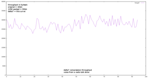
A test with a radio talk show shows practical gains in throughput of 33% on average. Here is the throughput over time:
Command channel
The command channel is an UDP port that the transmitter listens on, to receive such commands as:
- trigger data sending now for 15 seconds, regardless of the envelope detection
- enable or disable the digital highpass filter (it’s disabled by default and doesn’t improve sound quality, but I keep it to show that the ESP8266 can do nontrivial realtime signal processing)
- change the target from receiver to computer
- modify the threshold for the envelope detection
The very first command in particular can be used from the receiver, where a press on a button will trigger sound transmission.
Digital filter
I used mkfilter (modified to build on modern machines here) to implement a high-pass 5th order Butterworth filter with Fc=150Hz. As I know that there is no signal I am interested in below 150Hz (and probably below a much higher frequency than this, as baby cries are usually high pitched), I thought it might be interesting to add such a filter. It does consume quite a bit of processing power, about 15 milliseconds per 700 samples buffer, but it still works in real time. It is disabled by default because I didn’t find it to improve sound quality.
I2C communication
The receiver, as previously stated, uses an I2C DAC. I2C on the ESP8266 doesn’t exist in hardware, so it requires bit-banging, with the poor performance it implies. I copy pasted ESP8266-arduino’s I2C implementation and tweaked it a little for my uses - that turned out to run about 25% faster than the supposedly super-fast brzo_i2c. I’m sure brzo_i2c is useful for large I2C transfers, but for only 2 bytes at a time, it is a loss over Arduino’s implementation.
